Gujarat Technological University 2010-3rd Sem A.M.I.E.T.E Electronics & Communication Engineering Electronics and Communication Engineering Circuits and Network - Question Paper
GUJARAT TECHNOLOGICAL UNIVERSITY
B.E. Sem-III Regular / Remedial Examination December 2010
Seat No. Enrolment No.
Subject code: 130901 Subject Name: Circuits and Networks
Time: 10.30 am - 01.00 pm Total Marks: 70
Date: 14 /12 /2010
1. Attempt all questions.
Make suitable assumptions wherever necessary.
2.
3.
Figures to the right indicate full marks.
Q.1 (a) Explain the terms ( i ) Linear (ii) Bilateral ( iii) Passive (iv) Reciprocal
07
07
(v) Time invariant (vi) Lumped parameter and (vii) Dual with reference to Network. (b) Write down voltage and current relationships in resistor, inductor and capacitor. Obtain these relationships in s domain also. State assumptions if any in obtaining the relationship.
Q.2 (a) (i) Explain about voltage sources and current sources. Include ideal, practical, independent and dependent sources in your explanation.
04
03
07
07
07
07
07
07
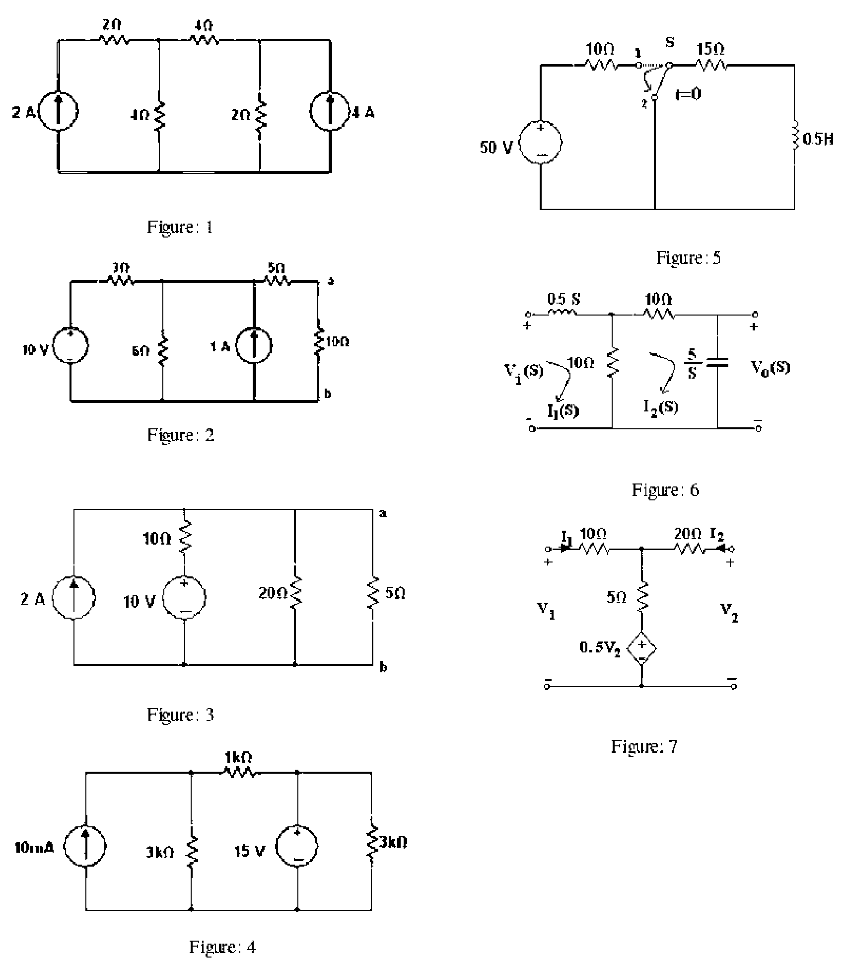
(ii) Using Nodal analysis find voltage V1 and V2 for the circuit shown in Figure 1.
(b) Explain in brief about source transformation and Find Nortons equivalent circuit for the network shown in Figure 2 and obtain current in 10Q resistor.
OR
(b) Obtain Thevenins equivalent circuit for the network shown Figure 3 and find the power dissipated in RL= 5Q resistor. Find RL for maximum power transfer from the source and compute maximum power that can be transferred i.e. Pmax.
Q.3 (a) Find the voltage across 1KQ resistor in the circuit shown in Figure 4, using superposition theorem.
(b) Obtain the response vC(t) and iL(t) for the source free RC and RL circuits respectively. Assume initial voltage V0 and initial current Io respectively.
OR
Q.3 (a) For the circuit shown in Figure 5, the switch S is at position 1 and the steady state condition is reached. The switch is moved to a position 2 at t = 0. Find the current i(t) in both the cases, i.e. with switch at position 1 and switch at position 2. (b) How do one classify that the given circuit is of first order or second order? Obtain second order circuit models for series RLC and parallel RLC circuits in time domain and in s domain.
Q.4 (a) Obtain the Laplace Transform for f1(t}=t and f2{t}= teat 07
(b) State the final value theorem of Laplace Transform and find the final value of the 07 function f(t} =5u(t} + 10e-t using final value theorem. Under what conditions the final value theorem cannot be used ? Give one example.
OR
Q.4 (a) What is an impulse function ? For the network function H(s) given below, Find the 07 impulse response h(t}.
1
H(s) = -
s2+ 4s +1
Q.5 (a) Find Z- parameters for the network shown in Figure 7. 07
(b) Explain about hybrid parameters for two port network and state where do one make 07 use of these parameters.
OR
Q.5 (a) ABCD parameters are also known as transmission parameters and they are derived 07 from the basic two port network parameters. Show that, for reciprocal linear time invariant two port network, AD-BC =1.
(b) Explain about linear oriented graph, Incidence Matrix and Circuit Matrix. Show 07 Kirchoffs Laws in Incidence Matrix formulation and Circuit Matrix formulation.
2
|
Attachment: |
| Earning: Approval pending. |