Kurukshetra University 2009 B.Tech Electronics and Communications Engineering Netwok analysis and synthesis - Question Paper
NETWOK ANALYSIS AND SYNTHESIS
PAPER :-EE-203 E
Roll No. *


BT-3/D<)y
NETWORK ANALYSIS AND SYNTHESIS Paper : EE-203(E)
Roll No. *
[Maximum Marks ; 100Time : Three Hours]
Nule : Attempt any fire questions, selecting at least one question from each unit* All questions cany equal marks.
LJNIT-I
I. (a) Establish a relationship bclween Fundamental circuit and Fundamental cutset matrix.
(It) Draw an oriented graph lor the network of Fig. 1 and develops KVL and KCL equation in matrix form using fundamental dieuit and cutset matrices.
C.
nmr
Fig. I
Assume al! element values to be unity with appropriate
ft+12
units.
(P.T.O-
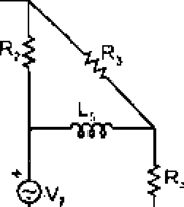
(a) The switch is suddenly moved to 2 at
an instant when the current in the network of Fig. 2 is 4A and the voltage across the capacitor is 9V. Draw the transformed circuit after the switching operation and hence or otherwise calculate the current ((/) for ( > 0,
1
f = D
-WV-
1011
-TST-
7H
at)
ir-
Veit)
0 v i't)
Fig. 2
{b) Unit impulse response of a circuit is e~K Determine the response of this circuit il input is [ti{() + u(t - 2}].
12+S
3. Determine transfer function G(j.> =
V2(-v)
V,(J)
for the network
shown in Fig, 3,
-w
1H
1H WV-
111
1F
*-VW-Hi
vz(0
UJ J -r-
*,(0
2q;
(a) '"flow frequency domain behaviour of a transfer function
can be obtained from the location of its pules anti zero's in the complex frequency plane?
(b) Plot pole-zeno config unit ion for ihe following network function
s + I
G (s) =
s1 + .la- + 2
JJ the network is excited by a source of value cost find the response of ihe network graphically? 8+12
(a) Define and determine Z and Y parameters for the symmetrical T network shown in Fig. 4.
2'
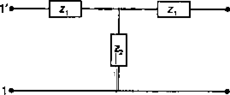
Fijj, 4
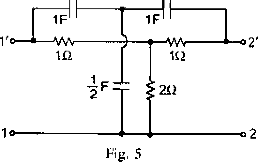
(b> Determine Y-parameters for The network of Fig, 5 using the knowledge gained in part (a).
Derive re I at ion ship between Transmission and Open circuit parameters of a 2-port nciwork. Prove ihal AD - BC = J for reciprocal passive networks.
Find (ransmission parameters for network of Fig. fi, MU
fa)
CM
-Wv-- -
-Wr
Wr
12
211
Fig. 6.
10+1 ft
UNIT-VI
7. Design a constant-K high-pass filler section having " fc"= I kH? and a load of dtKT Q! Calculate a and jl of your filler at 0. 500. 1000, 1500 and 2000 Hz, Derive relations used. 20
8, State line properties of L-C driving point impedance function, Show lhal the following impedance satisfies nil the properties staled anil synthesize it in two faster forms:
sis2 +2) s* + I Mr + 3}
Z(a) =
20
8l2GmOO/KD/W1 A
|
Attachment: |
| Earning: Approval pending. |