The Institution of Engineers,India 2005 A.M.I.E.T.E Electronics & Communication Engineering CIRCUIT THEORY & DESIGN - Question Paper
Code: A-08 Subject: CIRCUIT THEORY & DESIGN
Time: three Hours Max. Marks: 100
NOTE: There are 11 ques. in all.
• ques. one is compulsory and carries 16 marks. ans to Q. 1. must be written in the space given for it in the ans book supplied and nowhere else.
• ans any 3 ques. every from Part I and Part II. every of these ques. carries 14 marks.
• Any needed data not explicitly given, may be suitably presumed and said.
Q.1 select the accurate or best option in the following: (2x8)
a.
The poles of the impedance Z(s) for the network shown in Fig.1 beneath will be real and coincident if
(A) . (B) .
(C) . (D) .
b. The network shown in part a has zeros at
(A) s = 0 and s = . (B) s = 0 and s = .
(C) s = and s = . (D) s = and s = .
c. Of the 2 methods of loop and node variable analysis
(A) loop analysis is always preferable.
(B) node analysis is always preferable.
(C) there is nothing to select ranging from them.
(D) loop analysis may be preferable in a few situations while node analysis may be preferable in other situations.
d. In a double tuned circuit, consisting of 2 magnetically coupled, identical high-Q tuned circuits, at the resonance frequency of either circuit, the amplitude response has
(A) a peak, always. (B) a dip, always.
(C) either a peak or a dip. (D) neither a peak nor a dip.
e. In a series RLC circuit with output taken across C, the poles of the transfer function are located at . The frequency of maximum response is provided by
(A) . (B) .
(C) . (D) .
f. A low-pass filter (LPF) with cutoff at one r/s is to be transformed to a band-stop filter having null response at and cutoff frequencies at and . The complex frequency variable of the LPF is to be changed by
(A) . (B) .
(C) . (D) .
g. For an ideal transformer,
(A) both z and y parameters exist.
(B) neither z nor y parameters exist.
(C) z-parameters exist, but not the y-parameters.
(D) y-parameters exist, but not the z-parameters.
h. The subsequent is a positive real function
(A) . (B) .
(C) . (D) .
PART I
ans any 3 ques.. every ques. carries 14 marks.
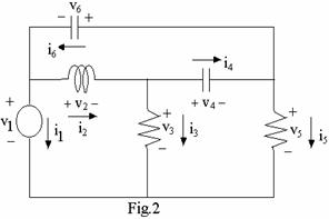
Q.2 a. In the circuit shown in Fig.2 below, it is claimed that . Prove OR disprove. (7)
b. A voltage source whose internal resistance is delivers power to a load in which is fixed but is variable. obtain the value of at which the power delivered to the load is a maximum. (7)
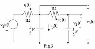
Q.3 In the circuit shown in Fig.3 below, . Using the corresponding phasor as the reference, draw a phasor diagram showing all voltage and current phasors. Also obtain and . (14)
Q.4 a. In the circuit shown in Fig.4 below, and . obtain the voltage . (7)
b. Determine the equivalent Norton network at the terminals a and b of the circuit shown in Fig.5 beneath. (7)
Q.5 In the network shown in Fig.6 below, and . The capacitor is charged to and connected across the network at t = 0. is initially uncharged. obtain an expression for . (14)
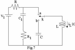
Q.6 a. The switch K (Fig.7) is in the steady state in position a for . At t = 0, it is connected to position b. obtain . (7)
b. A battery of voltage v is connected at t = 0 to a series RC circuit in which the capacitor is relaxed at t = . Determine the ratio of the energy delivered to the capacitor to the total energy supplied by the source at the instant of time t. (7)
PART II
ans any 3 ques.. every ques. carries 14 marks.
Q.7 Synthesize the admittance function in the form shown in Fig. eight beneath. (14)
Q.8 Synthesize an RC ladder and an RL ladder network to realize the function as an impedance or an admittance. (14)
Q.9 a. Determine the condition for which the function is positive real. It is provided that , and are real and positive. (10)
b. Determine the common factor ranging from the even and odd part of the polynomial . (4)
Q.10 a. In the network shown in Fig.9 below, obtain if (8)
b. Synthesize and if and R =1. (6)
Q.11 a. 2 two-port networks and are connected in cascade as shown in Fig.10 beneath. Let the z – and y parameters of the 2 networks be distinguished by additional subscripts a and b. obtain the and parameters of the overall network. (10)
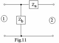
b. Determine the z-parameters of the network shown in Fig.11 beneath. (4)
Code: A-08 Subject: CIRCUIT THEORY & DESIGN
Time: 3 Hours Max. Marks: 100
NOTE: There are 11 Questions in all.
Question 1 is compulsory and carries 16 marks. Answer to Q. 1. must be written in the space provided for it in the answer book supplied and nowhere else.
Answer any THREE Questions each from Part I and Part II. Each of these questions carries 14 marks.
Any required data not explicitly given, may be suitably assumed and stated.
Q.1 Choose the correct or best alternative in the following: (2x8)
a.
|
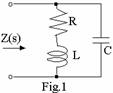
The poles of the impedance Z(s) for the network shown in Fig.1 below will be real and coincident if
(A) ![]() .
(B)
.
(B) ![]() .
.
(C)
![]() .
(D)
.
(D) ![]() .
.
b. The network shown in part a has zeros at
(A)
s = 0 and s = ![]() .
(B) s = 0 and s =
.
(B) s = 0 and s = ![]() .
.
(C) s = ![]() and s =
and s = ![]() .
(D) s =
.
(D) s = ![]() and s =
and s = ![]() .
.
c. Of the two methods of loop and node variable analysis
(A) loop analysis is always preferable.
(B) node analysis is always preferable.
(C) there is nothing to choose between them.
(D) loop analysis may be preferable in some situations while node analysis may be preferable in other situations.
d. In a double tuned circuit, consisting of two magnetically coupled, identical high-Q tuned circuits, at the resonance frequency of either circuit, the amplitude response has
(A) a peak, always. (B) a dip, always.
(C) either a peak or a dip. (D) neither a peak nor a dip.
e. In a series RLC circuit with output taken across C, the poles of
the transfer function are located at ![]() . The frequency of
maximum response is given by
. The frequency of
maximum response is given by
(A)
![]() .
(B)
.
(B) ![]() .
.
(C) ![]() .
(D)
.
(D) ![]() .
.
f. A low-pass filter (LPF) with cutoff at 1 r/s is to be
transformed to a band-stop filter having null response at ![]() and cutoff
frequencies at
and cutoff
frequencies at ![]() and
and ![]()
![]() . The
complex frequency variable of the LPF is to be replaced by
. The
complex frequency variable of the LPF is to be replaced by
(A)
 .
(B)
.
(B) ![]() .
.
(C)  .
(D)
.
(D)  .
.
g. For an ideal transformer,
(A) both z and y parameters exist.
(B) neither z nor y parameters exist.
(C) z-parameters exist, but not the y-parameters.
(D) y-parameters exist, but not the z-parameters.
h. The following is a positive real function
(A)  .
(B)
.
(B) ![]() .
.
(C) ![]() .
(D)
.
(D) ![]() .
.
PART I
Answer any THREE Questions. Each question carries 14 marks.
|
Q.2
a. In the circuit shown in Fig.2 below, it is claimed that  .
Prove OR
disprove.
(7)
.
Prove OR
disprove.
(7)
b. A voltage source ![]() whose internal resistance
is
whose internal resistance
is ![]() delivers
power to a load
delivers
power to a load ![]() in which
in which ![]() is
fixed but
is
fixed but ![]() is
variable. Find the value of
is
variable. Find the value of ![]() at which the power
delivered to the load is a maximum.
(7)
at which the power
delivered to the load is a maximum.
(7)
Q.3
In the circuit shown in Fig.3 below, ![]() . Using the
corresponding phasor as the reference, draw a phasor diagram showing all
voltage and current phasors. Also find
. Using the
corresponding phasor as the reference, draw a phasor diagram showing all
voltage and current phasors. Also find ![]() and
and ![]() .
(14)
.
(14)
|
Q.4
a. In the circuit shown in Fig.4 below, ![]()
![]() and
and ![]() . Find
the voltage
. Find
the voltage ![]() .
(7)
.
(7)
|

|
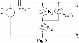
b. Determine the equivalent Norton network at the terminals a and b of the circuit shown in Fig.5 below. (7)
|
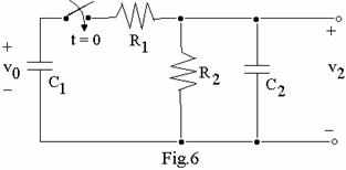
Q.5
In the network shown in Fig.6 below, ![]() and
and ![]() . The capacitor
. The capacitor
![]() is
charged to
is
charged to ![]() and connected across the
and connected across the ![]() network
at t = 0.
network
at t = 0. ![]() is initially
uncharged. Find an expression for
is initially
uncharged. Find an expression for ![]() .
(14)
.
(14)
Q.6 a. The switch K (Fig.7) is in
the steady state in position a for ![]() . At t = 0, it is
connected to position b. Find
. At t = 0, it is
connected to position b. Find ![]() .
(7)
.
(7)
|
|
|
|
|
|
|
b. A battery of voltage v is connected
at t = 0 to a series RC circuit in which the capacitor is relaxed at t = ![]() .
Determine the ratio of the energy delivered to the capacitor to the total
energy supplied by the source at the instant of time t.
(7)
.
Determine the ratio of the energy delivered to the capacitor to the total
energy supplied by the source at the instant of time t.
(7)
PART II
Answer any THREE Questions. Each question carries 14 marks.
|
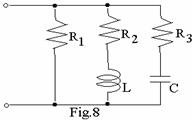
Q.7
Synthesize the admittance function ![]() in the form shown in Fig.
8 below.
(14)
in the form shown in Fig.
8 below.
(14)
Q.8
Synthesize an RC ladder and an RL ladder network to realize the function ![]() as an
impedance or an
admittance.
(14)
as an
impedance or an
admittance.
(14)
Q.9
a. Determine the condition for which the function  is
positive real. It is given that
is
positive real. It is given that ![]() ,
, ![]()
![]() and
and ![]() are
real and positive. (10)
are
real and positive. (10)
b. Determine the common factor between
the even and odd part of the polynomial ![]() .
(4)
.
(4)
Q.10
a.
In the network shown in Fig.9 below, find ![]() if
if ![]() (8)
(8)
|
|
|
|
|
|
|

b. Synthesize ![]() and
and ![]() if
if  and R
=1.
(6)
and R
=1.
(6)
|
Q.11
a.
Two two-port networks  and
and  are connected in cascade as shown
in Fig.10 below. Let the z and y parameters of the two networks be
distinguished by additional subscripts a and b. Find the
are connected in cascade as shown
in Fig.10 below. Let the z and y parameters of the two networks be
distinguished by additional subscripts a and b. Find the  and
and  parameters
of the overall
network.
(10)
parameters
of the overall
network.
(10)
b. Determine the z-parameters of the network shown in Fig.11 below. (4)
|
|
|
|
|
|
|
| Earning: Approval pending. |