Guru Gobind Singh Indraprastha Vishwavidyalaya 2007 B.E Mechanical Engineering MACHINE DESIGN - 1 (REAPPEAR) - Question Paper
END TERM exam
FIFTH SEMESTER [B.TECH] – DEC - 2007
MACHINE DESIGN - one (REAPPEAR)
(Please write your Exam Roll No. ) Exam Roll No.
End-Term Examination
Fifth Semester [B.Tech.] December-2007
|
Paper Code: ETME-303 (Batch-2002-2003) Paper ID: 200574 |
Subject: Machine Design-1 (Reappear) |
Maximum Marks: 75
Time3 Hours
Note: Attempt five questions in all, including Q.1, which is compulsory.
State and explain any four steps in a systematic design procedure. (6)
Where are ova! flanges used in pipe joints? Why are gaskets with targe radial widths not recommended for high pressure pipe joints? (4)
Answer true or false in relation to the following statements:
(j) Low carbon steei is used for socket end of a cotter joint. (1)
(ii) Rain wai." pipes carry water at a pressure of 20 atmospheres. (2)
(iii) The wire of a closely coiled helical spring develops, primarily, bending stress dti to axial.load. (2)
Detail steps to design double eye end of a knuckle joint. Also sketch freehand its top view and front view. (9) Are connecting rod and piston of an I.C. engine under fatigue loading? Explain notch sensitivity factor and fatigue stress concentration factor. (6)
Name any two 'breads, used for power transmission and also explain the reason for restrk r.ing the maximum value of lead angle in a power screw. (4) Design the scrow and nut for a screw jack, suitable for a maximum load of 5000 kgf and hiving a lift of 225 mm with a ground clearance of 40 cm.
For steel screvv. safe stresses in tension, shear and compression are 942. 648 and 1176 kgf. cm-2 respectively. Corresponding values for phasphor bronze nut are 628, 471 and 550 kgf. cm'2 respectively. Permissible value of bearing stress for threats being 157 kgf. cm'2, (11)
Sketch a double welded U-type butt joint and a double bevel butt joint. Also show the cross-i.3dion of a re-inforced weld. (5)
(a)
(b)
(c)
Q.1
Q.2 (a) (b)
Q.3 (a) (b)
Q.4 (a)
(b)
|
(vjM-JI- . L-J-L-j-i-1 ~ |
 |
|
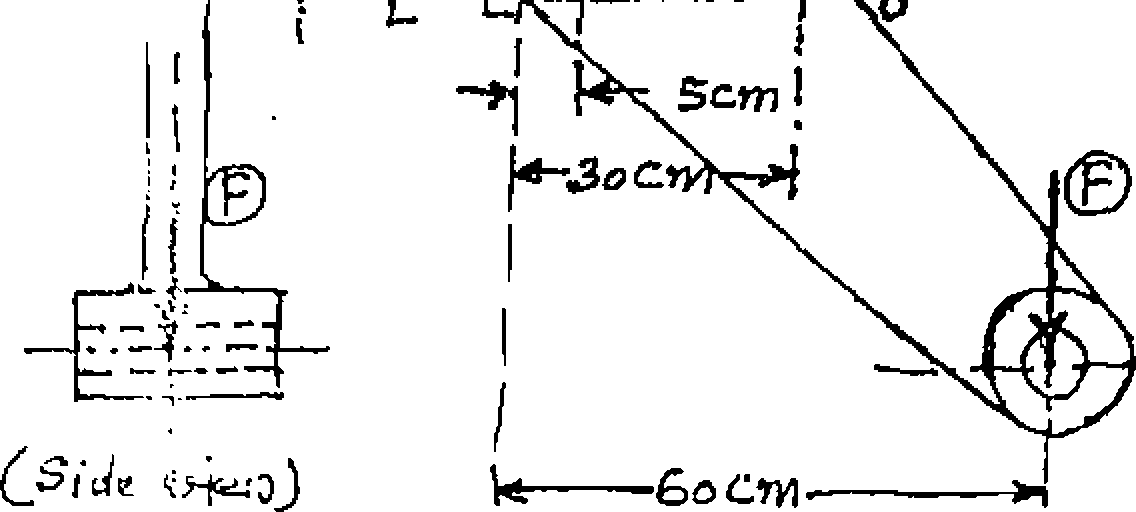
CF-fonb WejgJ Fig. 1 shows twc views of a bolted bracket to support a load F. It is fastened to the structure with four bolts of size M30, with a core diameter value of 27.706 mm. Determine the value of load which can be supported, with an allowable tensile stress of 800 kgf. cm ~2 in bolts. (10) |
p/rl
Explain Wahls ractor, used in the design of springs. Also state the range of spring index, used in the design of springs. (5)
(a)
no
(b)
Design a high pressure hydraulic flanged pipe joint with oval flanges, having two bolts, with the following data: (10)
Pipe bore = 75mm, working pressure = 140 kgf. cm-2
Allowable stress in pipe material = 780 kgf. cm"2
Allowable stress in bolt material = 650 kgf. cm ~2
Aflowable tensile stress in flanges = 800 kgf. cm ~2
Q.6 (a) (i) t Give any three applications of levers. (3)
(ii) Why are arms of a lever tapered? (2)
(iii) Explain with sketches as to which of the cross-sections, mentioned below are preferred for lever arms and why? (5)
(b) In a cotter joint assembly, why is the F.O.S. kept least for cotter? How is bending stress obtained for cotter? (5)
Q.7 (a) How do protected type of flanged couplings differ from unprotected type?
How are flanged couplings imparted the element of flexibility? (6)
 |
jb?tyopf |
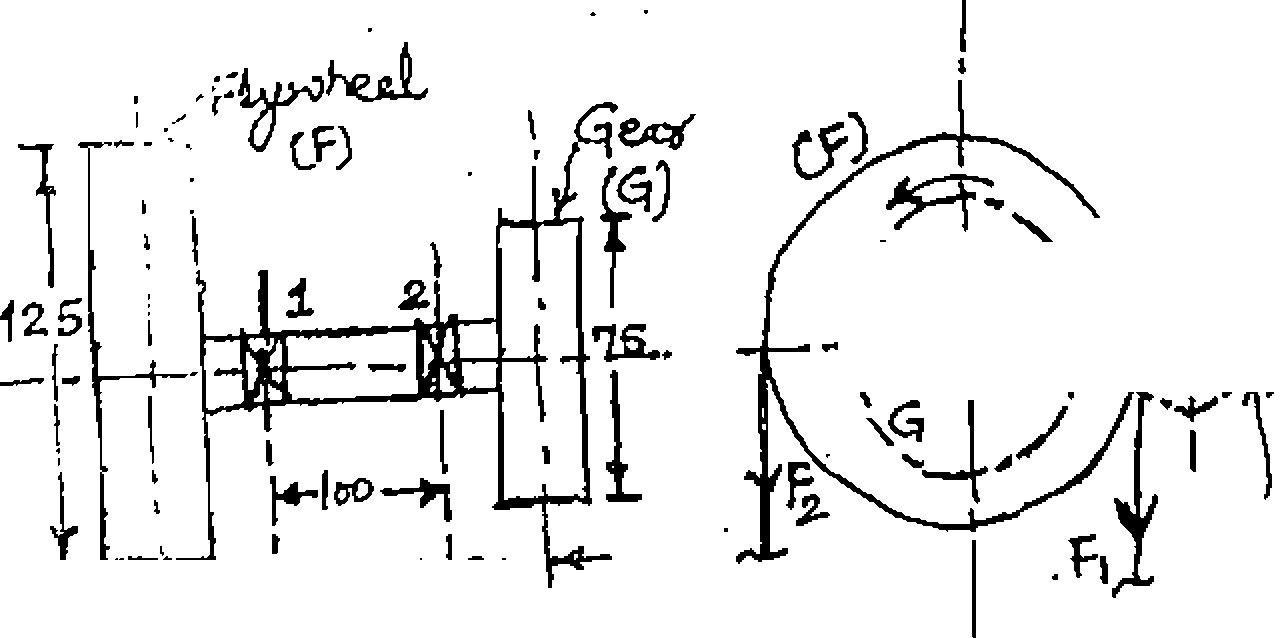
(b) The arrangement for a transmission shaft is shown in Fig 2. 25 horse power is received by gear G from pinion P, and is transmitted to an appliance through the flywheel F. All distances are in mm and the shaft rotates at 150 r.p.m.
The trangenliai 100th load for the mating tooth of gear G is vertically upward and the weigln of gear is 90 kgf. The flywheel F delivers the power vertically downward through a belt for which tension on the tight side (F,) is 2.5 times
the one on the slack side (F2). The flywheel weighs 270 kgf. Determine the
diameter of sk rt for a permissible shear stress value of 630 kgf. cm "2. Use shock fatigue factor for bending moment as 2.0 and for torque as 1.5. (9)
Q.8 (a) For a nominal diameter of 50 mm, give designations of a clearance fit and an interference fit, using the basic hole system. (4)
(b) A pair of parallel toothed spur gears, having 20 involute full' depth teeth, is to transmit 16 horse power at 300 r.p.m. of.pinion. The velocity ration is 3:1. The allowable static stresses for gear of C.l. and pinion steel are 600
kgf. cm : and 1050 kgf. cm 2 respectively. Assuming number of teeth on pinion to be 16 and face width as 14 times the module, determine the module, face width ana pitch circle diameters of the pinion and the gear. Take velocity
4.5
factor, C, = :-(V) being the peripheral speed of gear in m/sec) and Y
4.5 + V (tooth form factor).
(11)
U.I54-
0.912
No. of leeth
|
Attachment: |
| Earning: Approval pending. |