Cochin University of Science and Techology (CUST) 2007 B.Tech Civil Engineering Strength of Materials u - Question Paper
BTS -II- (S)-07-065
B. Tech Degree II Semester (Supplementary) Exa January 2007
(Common for 1996 & 1997 Admissions)
Maximum Marks : 100
Time : 3 Hours
I- (a)
(b)
Derive relationship between Youngs Modulus E, Shear Modules G and Poissons ratio fj,.
(5)
The following data were recorded during a tensile test of a 14.0 mm diameter mild steel rod. The gage length was 50.0mm.
|
Load (N) |
Elongation (mm) |
Load (N) |
Elongation (mm) |
|
0 |
0 |
46200 |
1.25 |
|
6310 |
0.010 |
52400 |
2.50 |
|
12600 |
0.020 |
58500 |
4.50 |
|
18800 |
0.030 |
68000 |
7.50 |
|
25100 |
0.040 |
69000 |
12.50 |
|
31300 |
0.050 |
67800 |
15.50 |
|
37900 |
0.060 |
65000 |
20.0 |
|
40100 |
0.163 |
61500 |
Fracture |
|
41600 |
0.433 |
(15)
Plot the stress-strain diagram and determine the following mechanical properties (i) proportional limit (ii) modulus of elasticity
(iii) yield point (iv) ultimate strength
(v) rupture strength
What is Mohrs Circle of stress? Explain.
The state of stress in a two dimensionally stressed body is shown in the figure. Determine the principal planes, principal stresses, maximum shear stress and their planes. . , t
]__
II.
(a)
(b)
(6)
(14)
IXoa/Ji
f>o
haKlfo
(a)
(b)
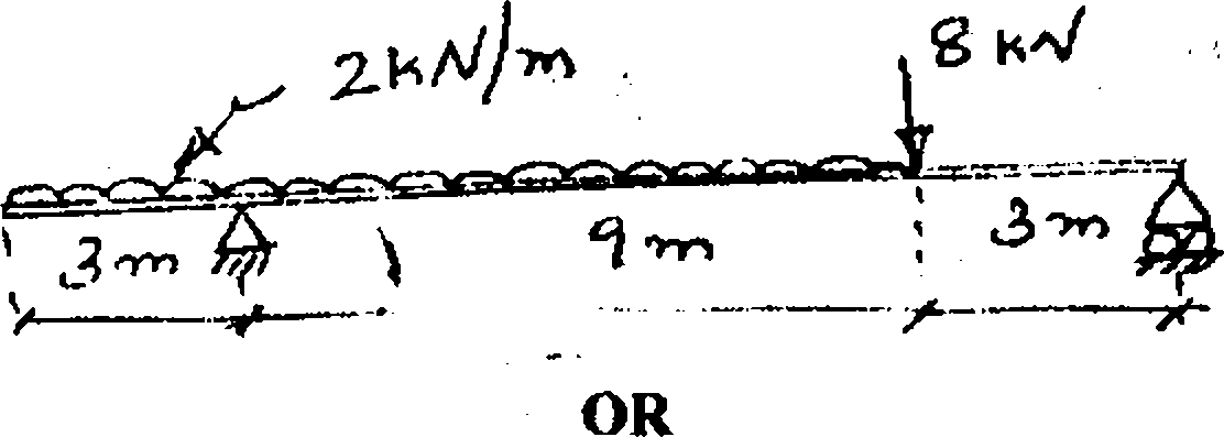
Obtain relations among load, shear and moment in a beam.
In the figure 2 is shown a overhanging loaded beam. Draw bending moment and shear force diagrams. Obtain the magnitude and position of maximum bending moment. Also locate the position of point of contra flexure.
III.
(5)
(15)
r'
*
(a)
(b)
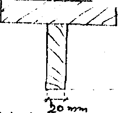
What are the assumptions made in the theory of simple bending?
The T-section shown in the figure is the cross-section of a beam formed by joining two rectangular pieces of wood together. The beam is subjected to a maximum shearing force of 60KN. Show that the Neutral Axis (N.A) is 34mm from the top and that
INA =10.57x10 mm
neutral axis and at the junction between the two pieces of wood. Also draw shearing stress variation diagram. -------
Using these values determine the shearing stresses at the
(16)
 |
/ O O trjyn |
V.
(a)
(b)
and deflection in a beam.
A simply supported beam is loaded by a couple M at its right end, as shown in the Figure. Show that the maximum deflection occurs at x 0.577/.
(8)
jr\W
T
I. I i 3
------------I.-
(12)
(5)
OR
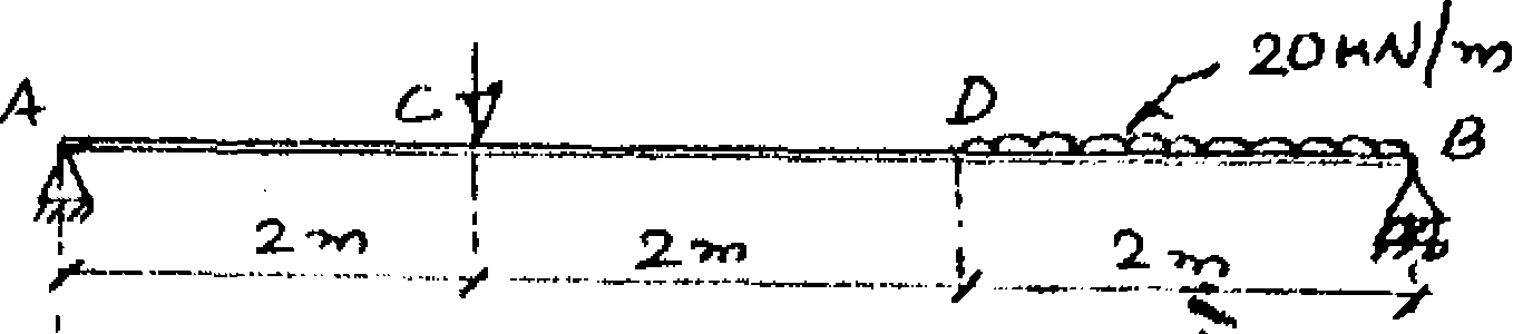
State and explain moment-area theorem.
Find the maximum deflection and the maximum slope for the beam as shown in the figure.
(a)
(b)
VI.
(15)
(6)
State assumptions made in deriving expression for bulking load of columns. Give its limitations also.
From the experiment on a steel strut the following results are available.
VII.
(a)
(b)
|
Test No. |
~ 1 ....... |
II |
|
Slenderness ratio |
70 |
170 |
|
Average stress at failure |
200N/mm2 |
69N/mm2 |
Assuming these two values are in agreement with the Rankines formula, find the two constants in the formula.
If the bar of same material having circular section of 40mm diameter and of length 1,2m is used as a strut with both ends fixed, find the safe load using the constants obtained.
Use a factor of safety of 4. (14)
OR
(Contd...3)
VIII. (a) Prove that a hollow shaft is stronger and stiffer than the solid shaft of the same material
length and weight. (10)
(b) Determine the diameter of wire of a close coil helical spring having the following properties.
(i) Stiffness = 5N/mm
(ii) Solid length = 100mm approximately
(iii) Permissible maximum shearing stress - 60N/mm2
(iv) Maximum load = 200N
(v) Modulus of rigidity = 80N/mm2.
Also obtain number of coils and radius of spring. (10)
IX. (a) Show that in thin cylinders the circumferential stress is twice the longitudinal stress
when it is subjected to internal pressure. (10)
(b) A pipe of400mm internal diameter and 100mm thickness contains a fluid at a pressure of 80N/mm2. Find the maximum and minimum hoop stresses across the section. Also sketch the radial and hoop stress distribution across the section. (10)
OR
X. (a) What is wire-wound cylinders? Explain. (5) (b) A 250mm diameter cast iron pipe has metal thickness of 10mm. It is closely wound
with 6mm diameter steel wire with an initial stress of 80N/mm2. Find the final stresses developed in cylinder and wire when fluid is admitted at 3N/mm2 pressure. (15)
|
Attachment: |
| Earning: Approval pending. |