Shivaji University 2011-6th Sem B.E Electrical Engineering T.E(Electrical)- (New), Power System Stability and Control - Question Paper
This is power system stability and control of third year electrical students of Shivaji University Kolhapur.
N - 754

Seat
No.
T.E. (Electrical) (Sem. - VI) (New) Examination, 2011 POWER SYSTEM STABILITY AND CONTROL
Day and Date: Wednesday, 18-5-2011
Total Marks: 100
Time: 2.30 p.m. to 5.30 p.m.
Instructions : I) Solve any three questions from Section ~ I and any three questions from Section -11.
2) Use of non-programmahle calculator is permitted.
3) Assume suitable data wherever necessary.
SECTION -1
1. A 60 Hz alternating voltage having a rms value of 100 V is applied to a series RL
circuit by closing a switch. The resistance is 15 Q and the inductance is 0.12 H.
a) Find the value of DC component of current upon closing the switch if the instantaneous value of voltage is 50 V at that time.
b) What is the instantaneous value of the voltage which will produce the maximum DC component of current upon closing the switch ?
c) Wrhat is the instantaneous value of the voltage which will results in absence of any DC component of current upon closing the switch ?
d) If the switch is closed when the instantaneous voltage is zero, find the instantaneous current 0.5, 1.5 and 5.5 cycles latter. 16
2. a) If ihe symmetrical components of voltages to neutral are
Vj = 50Z0, V2 = 20 Z90 and V0 = 10 Z180, determine the voltages to
8
neutral.
P.T.O.
N - 754
b) Obtain the relationship between the line and phase voltages and currents of symmetrical components for star and delta circuits. Draw neat phasor diagram.
-L-
3. a) Derive the sequence circuits for synchronous machine.
8
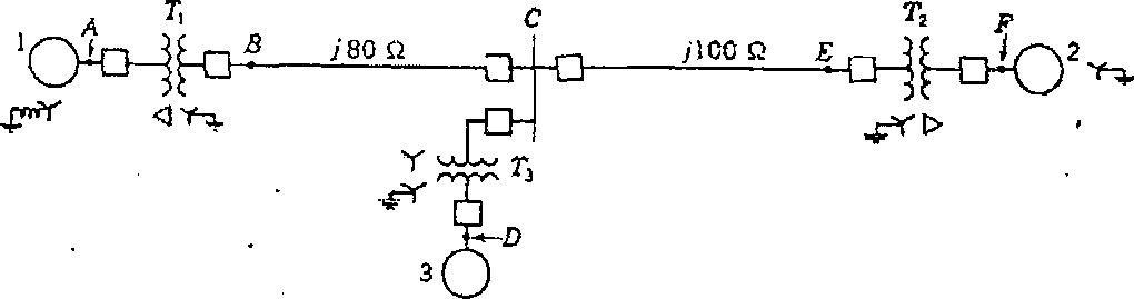
b) Obtain the zero sequence network of the power system shown in Fig. 1
Reactances of the two sections of the transmiission line are shown on the diagram.
The generators and transformers are rated as follows :
Gen 1 : 20MVA, 13.8 kV,Xd = 0.20 per unit Gen 2 : 30 MVA, 18 kV, Xd - 0.20 per unit Gen 3 : 25 MVA, 20 kV, Xd - 0.20 per unit Tj : 25 MVA, 220Y/13.8 A kV, X = 10%.
T2 : single phase units, each rated 10 MVA, 127/18 kV, X = 10%
T3 : 35 MVA, 220Y/22YkV, X = 10%
The neutral of Gen. 1 and 3 are connected to ground through current limiting reactors having reactance of 5%, each on the base of the machine to which it is connected. Each generator has zero sequence impedance of 5% to its base.
The zero sequence reactance of transmission line is 210Q from B to C and 250 Q from C to E.
Select the system base as 50 MVA. 10
Fig.l : Power system for Q. 3.b)
N - 754
-3-
4. a) Discuss the method of analyzing line to line faults.
8
8
b) What is need of AGC ? Explain AGC for single area.
SECTION - II
5. a) Derive the formulation for economic dispatch neglecting losses and no generator
limits for the generating plant with n units.
8
b) The fuel cost functions for three thermal units in a plant in Rs./h are given by : CSOO + S.SPO.OCMPj2 c2 = 400+ 5.5 Pj+ 0.006 P22 C3 = 200 + 5.8 Pj + 0.009P32
Where P, P2, and P3 are in MW. The total load PD, is 800 MW. Neglecting line losses and generator limits, find the optimal dispatch and total cost in Rs./h. 10
6. a) With suitable example explain optimal unit commitment. 8
b) For the economic operation of thermal plants including transmission losses prove that for 1th generating plant.
(ic)i = 'ki [l-onoj]
Where
(IC)j = incremental cost of ith plant
Xi = Lagrangian multiplier for ith plant
(ITL)t = incremental transmission loss for i* plant.

N - 754
-4-
7. a) State and prove the swing equation from the first principles of rotor dynamics. 8
b) The single line diagram of system is shown in Fig. 2. The machine is delivering 1.0 per unit power and both the bus voltages are 1.0 per unit. Numbers on the diagram indicates the values of the reactances on a common system base.
The transient reactance of the generator is 0.20 per unit as indicated. Determine the power angle equation for the given system operating conditions. 8
jtu
-Q

JO. A

O
Fig. 2 single line diagram for Q7. b)
8. a) Explain the methods of improving voltage stability of a system,
8
b) What is the need of contingency analysis of a power system ?
8
|
Attachment: |
| Earning: Approval pending. |