Manipal University 2007 B.E Electrical and Electronics Engineering THIRD SEMESTER MAKE-UP (REVISED CREDIT SYSTEM) 05 ELECTRICAL CIRCUITS ( ELE 201 - Question Paper
THIRD SEMESTER B.E. DEGREE MAKE-UP exam
(REVISED CREDIT SYSTEM)
05 January 2007
ELECTRICAL CIRCUITS ( ELE 201
Department of Electrical and Electronics Engineering
Reg. No.:
MANIPAL INSTITUTE OF TECHNOLOGY, MANIPAL
(A Constituent Institute of MAHE, Deemed University)
THIRD SEMESTER B.E. DEGREE MAKE-UP EXAMINATION
(REVISED CREDIT SYSTEM)
05 January 2007 ELECTRICAL CIRCUITS ( ELE 201 )
Time: 3 hours Max. Marks: 50
Note: Answer any FIVE full questions.
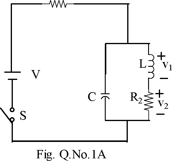
Q1A. In the network shown in Fig Q.No 1A, the switch is closed at t=0. Assuming zero initial conditions, find
i. vi and v2 at t = 0+ and at t=rc>
ii. dv1/dt and dv2/dt at t= 0+.
-05-
Q1B. For the circuit shown in Fig. Q.No.iB, construct a tree in which V1 and V2 are the tree branch voltages. DetermineV1 using cut set analysis.
-05-
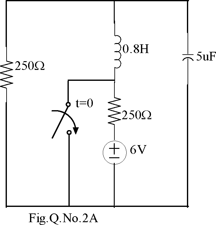
Q2A. A communication system from a space station uses short pulses to control a robot operating in space. The transmitter circuit is modeled as in Fig. Q.No. 2A. Find the output voltage vc(t) for t>0. Assume steady state condition at t=0 -.
-06-
Q2B. Find the branch currents io through i4 for the circuit shown in Fig. Q.No. 2B. using
mesh current analysis -04-
Q3A. Deduce the expressions for half power frequencies of a series RLC circuit. Also, show that the resonant frequency is the geometric mean of half power frequencies.
-05-
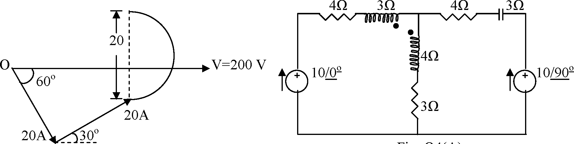
Q3B. For the locus diagram shown in Fig.Q No. 3B, draw the circuit configuration showing the element values. Also, find the value of R at unity power factor.
-05-
Q4A. For the circuit shown in Fig. Q. No.4A, find the voltage across the 4 Q reactance using superposition theorem. Assume XM = 2 Q. -07-
Q4B. Using admittance method, show that the circuit shown in fig.Q 4B, will not resonate for any value of XL. Also, draw the locus diagram. -03-
Q5A. For the circuit shown in Fig Q.No.5A, determine the current flowing in the 5 Q resistor using Nortons theorem.
-06-
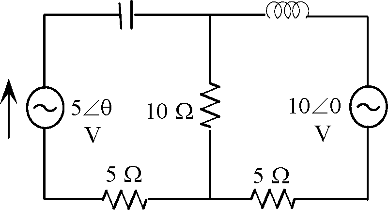
Q5B. For the circuit shown in Fig.Q.No.5B, determine 9 such that max power is transferred to the 10Q resistor. -04-
Q6A. A 3, 3 wire, RYB sequence supply system supplies power to a star connected load consisting of Zr = 10Z0 Q, Zy = 15Z300 Q and Zb = 10Z-300 Q. If Vbc = 208Z00 V, determine the line currents and the total power consumed using the mesh current method. Also draw the phasor diagram representing all the quantities. -05-
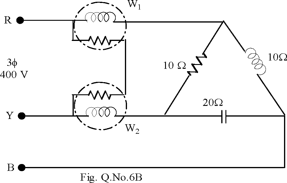
Q6B. For the circuit shown in Fig.Q.No.6B, determine the readings of the two wattmeters assuming an RYB phase sequence. -05-
|
Ri |
 |
5Q
-vwv
M-
80V
10Q
tVWV-
+ Vi -
Fig. Q.No.iB
2A
+ V2 -
50Q
(Z)20V
|
7i2 | ||
|
100V | 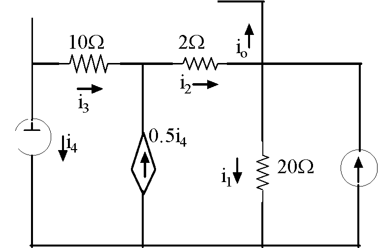 |
6.5A |
|
Fig. Q.No.2B | ||
 |
|
Fig. Q4(A) |
Fig. Q3(B)
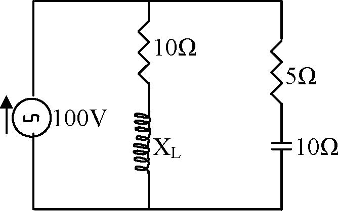
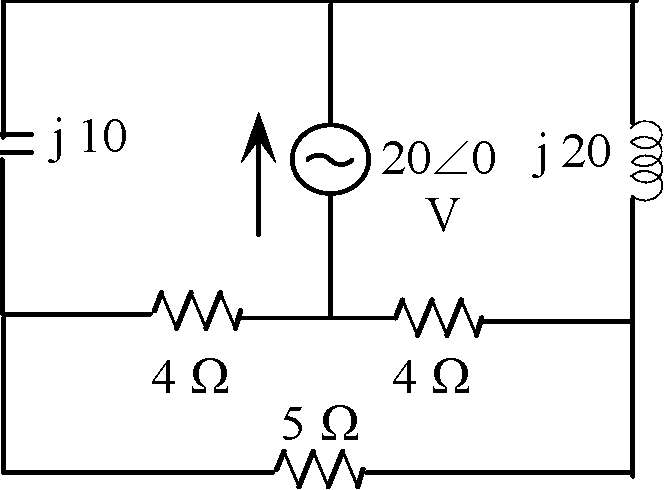
Fig. Q4(B)