Maharashtra State Board of Technical Education 2008 Diploma Mechanical Engineering Strength of Material - Question Paper
Course Name
Course code
Sample Question Paper - I
- Mechanical Engineering Group
- ME/ AE
- Third
Semester
Subject
Duration
- Strength of Material
- 3 hours
Marks: 80
Q.1 ] Attempt any eight of the following
8 X 2 (16)
a) Draw stress-strain diagram for ductile and brittle material.
b) Explain Pure bending with neat sketch.
c) State the Radius of Gyration.
d) State the core or kernel of section.
e) Define principle plane and principle stress.
f) State the equation of Torsion.
g) Define the limit of proportionality.
h) Define the contraflexure of loaded beam.
i) Sketch the cone of a section for hollow circular section.
j) Define temperature stress with example.
Q.2 ] Attempt any three of the following 3 X 4 (12)
a) State the values of effective length of column for following end condition. i) Both ends hinged ii) Both ends fixed.
b) State the expression for strain energy stored in a body due to gradually applied load.
c) A bar of 30 mm diameter is subjected to a pull of 60 kN. The measured extension on a gauge length on gauge length of 200 mm is 0.09 mm and change in diameter is 0.039 mm. Calculate the poissons ratio and modules of elasticity.
d) A load of 100 N falls by gravity through a vertical distance of 300 mm on to a collar at the end of the rod of length 6 m and 20 mm diameter. Find the maximum stress induced in the bar. Take E = 210 KN/mm2
Q.3 ] Attempt any three of the following 3 X 4 (12)
a) State the relationship between youngs modules and bulk modules.
b) State the value of maximum shear force and bending moment for a simply supported beam of a span L carrying a central point load.
c) A straight length of a steel bar, 1.5 m long and 2 cm x 0.5 cm section is compressed longitudinally until it buckle. Assuming Eulers formula to apply to this case, Estimate the maximum central deflection before the steel passes the yield point at 320 MPa. Take E = 210 GPa.
d) A simply supported beam of a span 7 m carries a UDL of 2 KN/m over 4 m length from the left support and appoint load of 5 KN at 2m from the right support. Draw SF and BM diagrams.
Q.4 ] Attempt any four of the following 4 X 4 ( 16 )
a) State Hookes law and Poissons ratio.
b) State the parallel axis theorem of Moment of Inertia.
c) Draw bending moment and shear force diagram of a cantilever beam AB, 4 m, long having its fixed end at A, and loaded with uniformly distributed load of 1 KN/m 2 m from B, and with a concentrated load of 2 KN at 1 m from A.
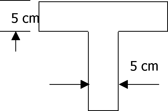
d) Calculate the moment of inertia of a T-section about the horizontal and vertical axis passing through a centre of gravity of a section as shown in Figure 4.1.
I
 |
|
Figure 4.1 e) A hollow circular chimney of 3m external and 1.5 m internal diameter is subjected to an average wind pressure of 5 KN/m2 . Find the maximum height of the chimney so that no tension is produced on the base. Assume density of chimney material 20000 |
t
5 cm 15 cm
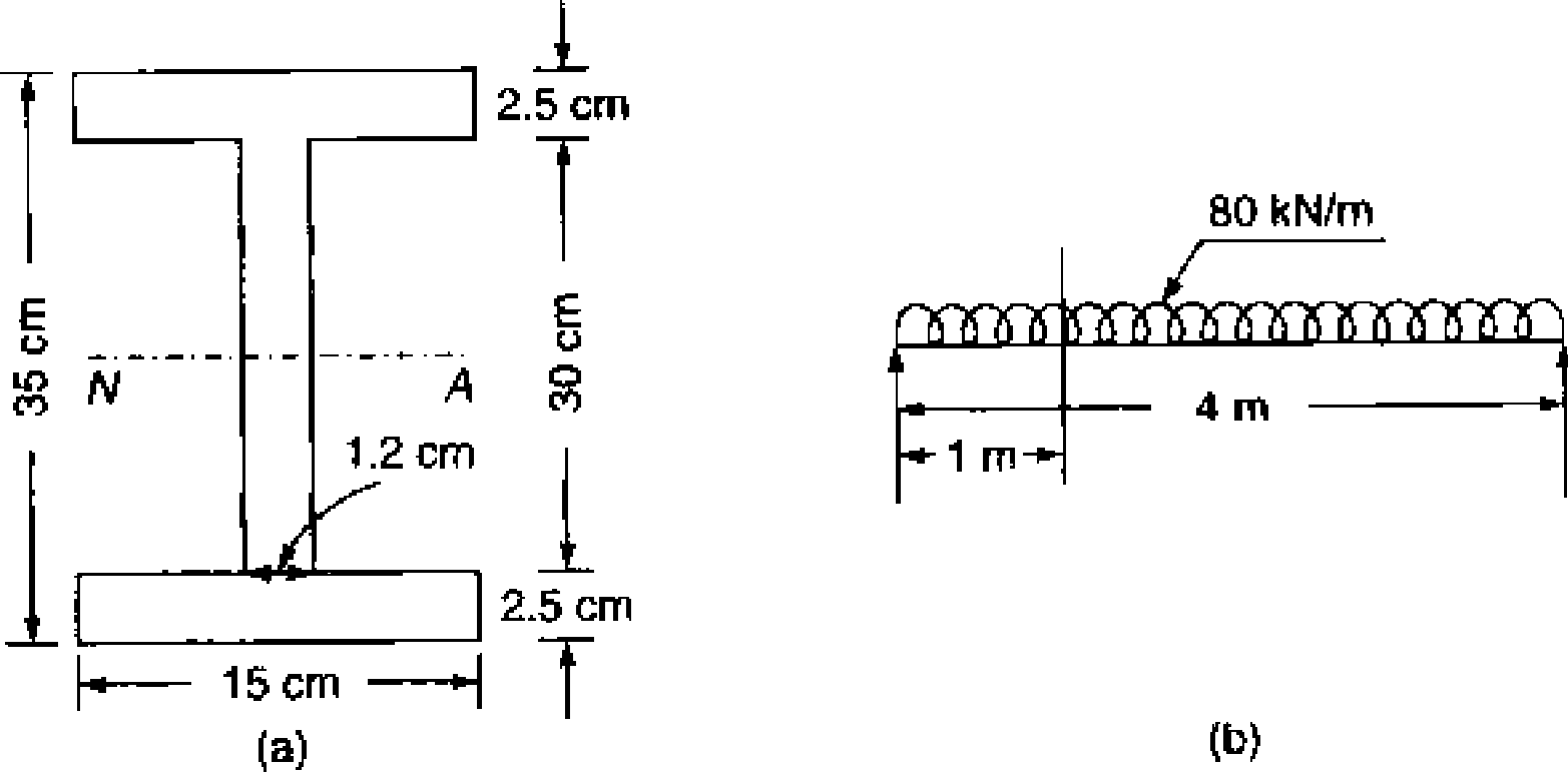
f) A rolled steel joist, simply supported across a span of 4m and carrying a uniformly distributed load of 80 KN/m, has the following dimension, overall depth 35 cm, each flange 150 mm x 25 mm and web 300 mm x 12 mm. Determine the magnitude of bending and shearing stresses at the function of web with the top flanges at the section
1 m away from the support.
 |
|
Figure 4.2 |
Q.5 ] Attempt any three of the following
3 X 4 (12 )
a) State any four assumptions in the theory of simple bending.
b) i) Define MI and state its SI units. ii) Define the term Limit of Eccentricity
c) A simply supported beam of a span 5.8 m is having a cross section of 200 mm wide and
500 mm deep. Calculate the intensity of uniformly distributed load the beam can carry if the bending stress is not to exceed 25 N/mm .
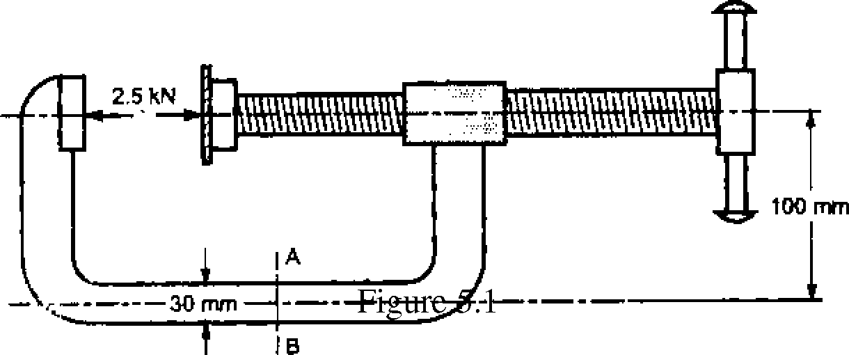
d) A C-clamp made up of a rectangular cross section 30 x 10 mm as shown in the figure is
subjected to a force of 2.5 KN. Find the stresses induced at section AB.
a) Derive a relation for normal and shear stresses of an oblique plane at an angle 0 from a plane where a direct stress ox acts.
b) A solid circular shaft of 100 mm diameter is transmitting power of 100 kw at 150 r.p.m.
Find the intensity of the induced shear stress in the shaft.
c) i) State the equation of torsion ii) How the power of shaft can be calculated.
d) Find the principle stresses and principle planes for a rectangular block subjected to stresses as shown in the figure 6.1 by Mohrs diagram. Also find the magnitude of maximum shear stresses. Also check the result by analytical method.
q

0x4
4
|
Attachment: |
| Earning: Approval pending. |