Maharashtra State Board of Technical Education 2008-4th Sem Diploma Industrial Electronics Power Electronic- - Question Paper
Course Name 9074
Sample Question Paper-I
: Industrial Electronics
Course Code
: IE
: IV
Semester
Title of the Subject : Power Electronic
Time : 3Hrs.
: 80
Max Marks
Instructions:
1. All questions are compulsory.
2. Illustrate your answers with neat sketches wherever necessary.
3. Figures to the right indicate full marks.
4. Assume suitable data if necessary.
5. Preferably, write the answers in sequential orders.
A) Attempt any four. 08 Marks
Q.1.
1) Draw & label the symbols of
1) GTO 2) SUS 3) SCS 4) LASCR
2) Draw the circuit of UJT oscillator triggering SCR.
3) What is forced commutation? List methods of forced commutation.
4) Draw the circuit of Class B commutation of SCR.
5) Draw ideal characteristics of suitch. What is the on state voltage of ideal switch.
B) Attempt any two . 08 Marks
Q.1.
a) i) Define the terms with respect to SCR
1. Holding current
2. Latching current
ii) Given SCR is in ON state, if anode current is reduced continuously, state at what current SCR turns off.
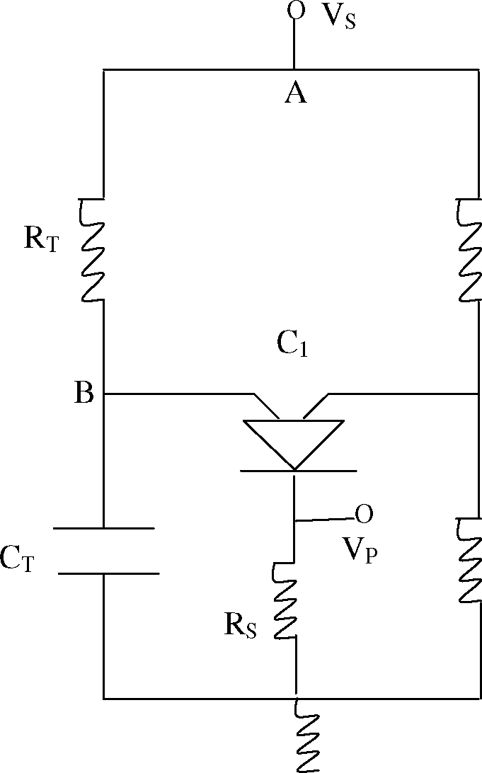
b) Study the circuit diagram and answer the following.
1. Identity the circuit
2. State the expression for output frequency.
3. Find the of frequency of output.
Rt = 1m, Ct = 0.1 f Ri = 24 m, R2 = 12m
 |
Ri R2 |
c) State the four modes of operation of Triac. Which are the efficient modes and why?
Q.2. Attempt any three. 12 Marks
a) Draw transistorized equivalent circuit of SCR. State its operation.
b) Why Diac is used to trigger triac? Draw the relevant circuit diagram.
c) Why the triggering mechanism Vak > Vbo is not used in controlled rectifier.
d) State the meaning of finger voltage of SCR. In parallel combination of two SCRs , State
the effect of difference in finger voltage on operation of SCRs
Q.3. Attempt any three. 12 Marks
a) Draw circuit of symmetrical half controlled 1 bridge rectifier. Draw wave forms of
1. Input voltage 2. Firing pulse
3. Load current 4. Load voltage
b) Draw power flip flop using SCR. State its working
c) With what modification the given circuit will work as one of the standard commutation.
Explain the operation of modified circuit.
d) Draw circuit of Triac as static ac switch. What are the merits of triac static switch over SCR static switch.
ScR1
ScR2
Vs
Rl
Q.4. Attempt any two. 16 Marks
a) Draw circuit of flasher using SCRs. State its working. State one application of it.
b) Draw circuit of 3 controlled half wave rectifier. State the meanings and condition for continuous conduction and discontinuous conduction operation. Draw the corresponding wave forms
 |
T |
1) Identify the circuit.
2) What is the effect of increase in R on load Justify.
3) Modify the circuit to control speed of ac motor.
Q.5. Attempt any three. 12 Marks
a) Define with respect to GTO.
1. Maximum controllable anode current.
2. Maximum gate to cathode reverse voltage.
b) In a circuit the operating current is 800 A and operating volage is 1000 V. The available SCRs are with maximum current rating 200 A and voltage rating 500V. Using available SCRs how above circuit can be developed?
c) What will happen if anode current is more than rated value of maximum controllable anode current? Why PUT is called programmable UJT? How it is programmed.
d) Draw circuit of single phase controlled bridge rectifier with inductive load. Stated its working.
|
Q.6. Attempt any three. 12 Marks |
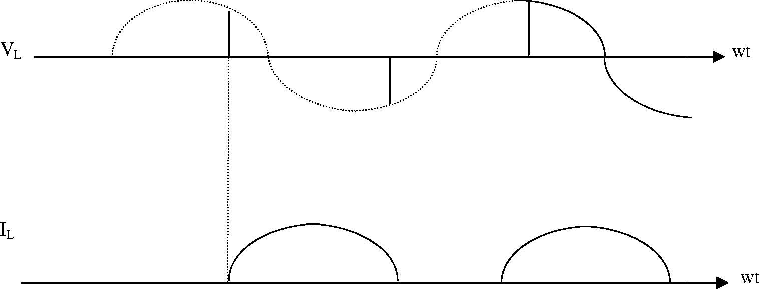 |
a) It is desired to obtain the above IL & VL wave forms suggest the appropriable rectifier circuit with load. Draw the circuit and state type of the quadrant operation
b) What are the conditions for commutation of SCR?
c) Draw circuit of Mc Murray Bed ford commutation method to commutate SCR. State its
operating principle
.d) How dc output voltage is controlled in single phase half wave rectifier. Give expression for dc output voltage & rms output voltage.
|
Attachment: |
| Earning: Approval pending. |