Maharashtra State Board of Technical Education 2008 Diploma Electrical and Electronics Basic Electronics - Question Paper
Sample Question Paper - I
:- Electronics Engineering group :- EE/EP/ET/EJ/EN/EX/IE/IS/IC/DE/MU/IU/ED/EI :- Third
Course Name Course code Semester Subject Duration
:- Basic Electronics
:- 3 hours Marks: 80
Instructions:
1. All questions are compulsory
2. Illustrate your answers with neat sketches wherever necessary
3. Figures to the right indicate full marks
4. Assume suitable data if necessary
5. Preferably, write the answers in sequential order
Q. No. 1 Attempt Any EIGHT of the following Marks 16
a. State the minority and majority carriers in N type and P type semiconductors.
b. What is the meaning of term rectification? State its need.
c. Draw constructional diagram for N channel JFET.
d. State the need for biasing a transistor when used as an amplifier.
e. Define load and line regulation with respect to regulator.
f. Draw CB and CC configuration of BJT. List one application of CB and CC amplifier.
g. State operating principle of LED.
h. Which filter is practically preferred to get pure DC output? Draw the circuit diagram of the same.
i. Why an ordinary junction transistor is called a bipolar device?
j. State the meaning of small signal amplifier. List two applications of it.
Q. No. 2 Attempt Any THREE of the following Marks 12
a. For a PN junction diode, applied voltages are 0V, +5V, -10V. Draw the PN junction indicating relative width of depletion region in each case.
b. Define the terms Static and Dynamic resistance of diode. What will be static resistance of the diode operated at 0.67 V and 2m
c. Compare centre tap and bridge rectifier on the basis of
1. TUF 2. PIV 3. No. of diodes 4. Ripple frequency
d. Give four important features of IC723. What is the use of CL & CS terminals?
a. With respect to JFET define:
1. Drain resistance 2. Transconductance 3. Amplification factor.
4. Give mathematical relation between them.
b. Derive the relation between a and P with respect to BJT.
c. What is meaning of the term heat sink? What is the significance of its physical structure? Draw a neat sketch of typical heat sink.
d. Draw two stage R-C coupled amplifier. Draw its frequency response.
Q. No. 4 Attempt Any FOUR of the following Marks 16
a. Explain on the basis of operating principle, how LED is different from an ordinary PN junction diode?
b. Draw circuit diagram of Half wave rectifier with capacitor filter. What is the peak inverse voltage across the diode with and without capacitor connected?
c. Compare CB and CE configuration on the basis of -
1. Input dynamic resistance 2. Output dynamic resistance. 3. Current gain 4. Leakage current
d. Draw the diagram for emitter bias method for BJT. Describe its operation.
e. Why different stages of amplifier are cascaded? State different methods used for cascading.
f. (i) Give units of hie, hfe, hoe, hre.
(ii) Draw the pin diagram of IC723.
5 Attempt Any THREE of the following Marks 12
Q. No.
a.
b.
c.
d.
Construct a dual power supply capable of giving 15V using 78xx and 79xx series ICs.
Draw the circuit diagram of CB amplifier. Give its one application.
For a given CE amplifier, output voltage Vo = 2V, input voltage Vin = 20mV find out its gain in dB. Calculate half power point.
Draw experimental set up to obtain diode characteristics. State function of each element in set up.
Q. No. 6 Attempt Any THREE of the following Marks 12
a. Compare CC and CE amplifier on the basis of
i). Input impedance ii). Current gain iii). Power gain iv). Input - output phase relation.
b. A n filter with FWR has C1 = C2 = 50f and L = 5H. The load current is 0.250mA at 50V DC.
c. Find the ripple factor.
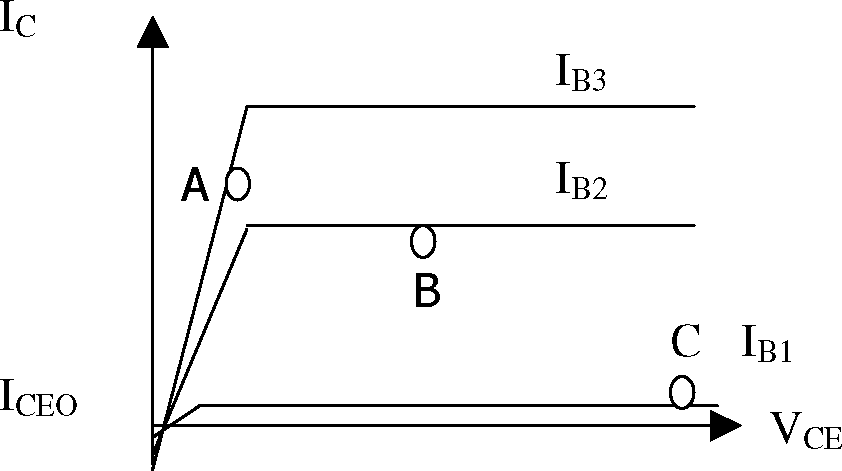
d. Identify the following characteristics. State in which region transistor is operated at point A, B and C.
e. Study the following fixed bias circuit.
|
O Vcc = 6V |
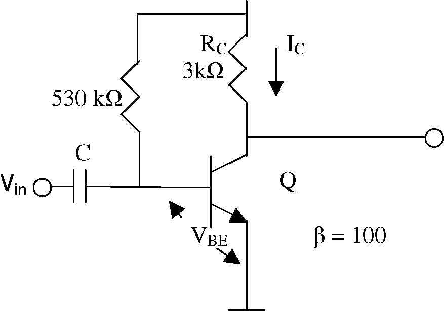 |
Draw the D.C. load line & determine the operating point.
|
Attachment: |
| Earning: Approval pending. |