Veer Narmad South Gujarat University 2010 B.E Strength of Materials - 1 - 2 ( Sem3 )( Chemical ) - Question Paper
RN-6127
B. E. - II (Sem. Ill) (Chemical) Examination May/June - 2010 Strength of Materials - I
Time : 3 Hours]
[Total Marks : 100
Instructions :
Seat No.:
M CnsLLnlcj.L{l [qoicu u? snqw <h>h41.
Fillup strictly the details of signs on your answer book.
Name of the Examination :
B. E. - 2 (Sem. 3) (Chemical)
Name of the Subject:
Strength of Materials - 1
|
-Subject Code No. |
|
-Section No. (1,2,.....) |
Student's Signature
1&2
(2) Answers to the two sections must be written in separate answer books.
(3) Figures to the right indicate full marks.
(4) Assume any additional data if required and mention them clearly.
(5) Justify your answers with suitable diagrams.
1 (a) Fill in the blanks : 5
(i) The diagram which represents the variation of shear force throughout the length of beam is termed as _.
(ii) Resistance to impact is called as _.
(iii) The ductility of C.I. is _ than that of steel.
(iv) Poisson's ratio is the ratio of _ strain to
linear strain.
(v) Relation between Young's modulus and bulk modulus is given by _.
Type of Test perform
(a) Hardness
Name of M/c.
(i) U.T.M.
(ii) Torsion
(iii) B.H.N. - V.H.N.
(iv) Carpy impact
(b) Endurance limit
(c) Modulus of rupture
(d) Rigidity
(e) Toughness
(v) F atigue
6
14
(c) Define the following : (any two)
(1) Strength (2) Brittleness
(3) Point of contraflexure (4) Hardness.
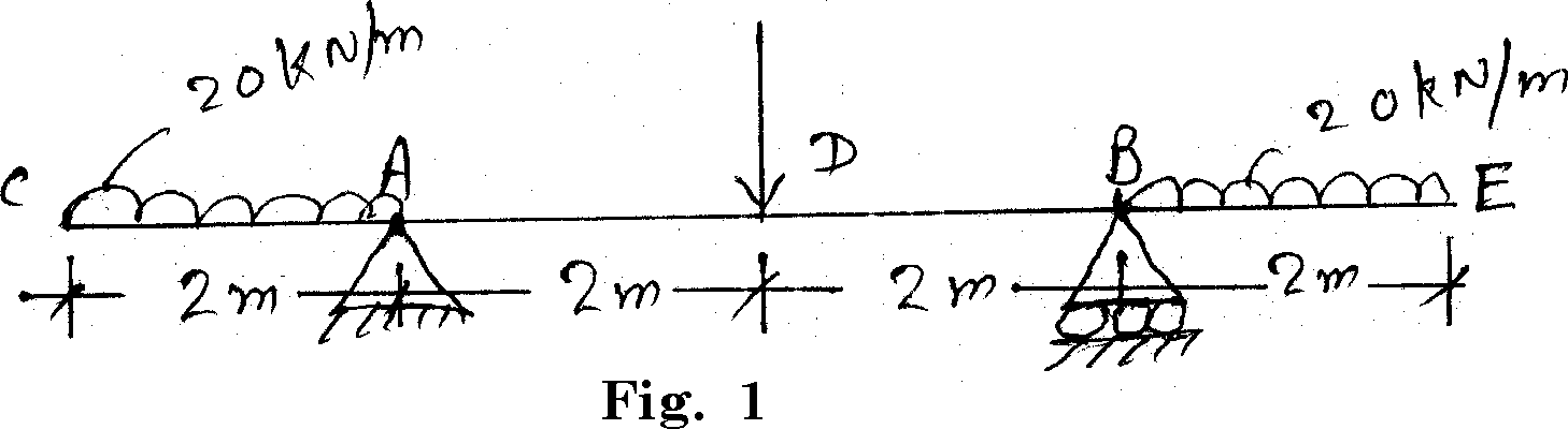
Draw S.F.D. and B.M.D. for the beam as shown in figure no. 1. Also find the point of contraflexure if any.
Attempt any two : 20
(i) A steel shaft transmits 105 kW at 160 r.p.m. If the shaft is 100 mm in diameter, find the torque required and maximum shearing stress induced. Find also the twist of the shaft in a length of 6 m. Take c = 8 x 10⁴ N/mm2. Find the elongation of the bar as shown in figure no.2.
|
(ii) | |
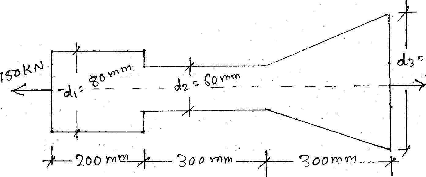 |
I Q-0 Wrr? Fig. 2 |
Take E = 2 x 10⁵ N/mm2.
(iii) Derive the equation for the deformation of uniformity tappering bar subjected to axial force P.
(iv) Derive the equation for volumetric strain of a rectangular bar, subjected to three mutually perpendicular forces.
|
Failure Pattern |
Name of test | ||
|
(i) |
Cut into two pieces |
(a) |
Compression |
|
(ii) |
Flat surface |
(b) |
Torsion |
|
(iii) |
Cup and Cone |
(c) |
Tension |
|
(iv) |
Twisted Fibre |
(d) |
Charpy Impact |
|
(v) |
Bulging-Buckling |
(e) |
F atigue |
|
Fill |
in the blanks : | ||
(b)
At Neutral axis value of bending stress is_.
(i)
(ii)
Stiffness of the spring can be defined as a ratio of_.
(iii) The equation of torsional strength is _.
(iv) S.N. diagram is plotted in _ test.
(v) In simply supported beam maximum bending moment occurs at _.
Attempt any two :
18
(i) A hollow cylindrical C.I. column is 4 m long with both end hinged. Determine inside and outside diameter of column if it is subjected to an axial load of 300 kN. Use Rankine's formula.
(Inside dia. = 0.8 x outside dia), fc = 550 N/mm2, a = 1/1600.
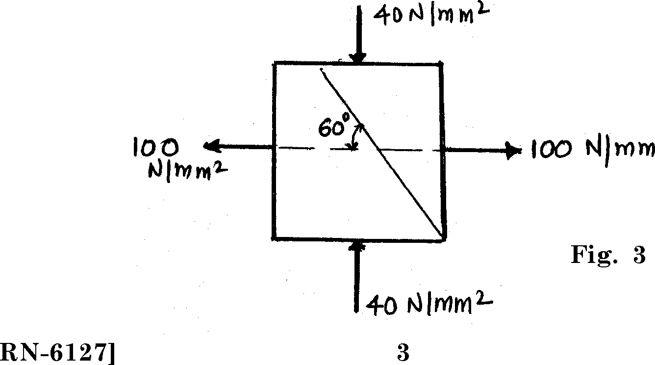
At a point in a strained material, the principal stresses are 100 N/mm2 tensile and 40 N/mm2 compressive. Determine the resultant stress in magnitude and direction on a plane inclined at 60 to the axis of the major principal stress. Also determine maximum intensity of shear stress in the material, (figure 3)
(ii)
(a) Sketch the shear stress variation across the rectangle, I and T beam.
(b) Equation of Torsional strength with all notations.
(c) Toughness and Hardness.
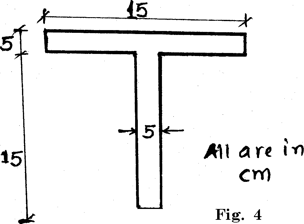
6 (a) A T shaped beam shown in figure 4. If a bending 11 moment of 3400 N.m. is applied around the horizontal neutral axis. Determine the bending stresses at top and bottom fibre of the beam. Nature of bending moment is sagging also plot bending stress distribution diagram.
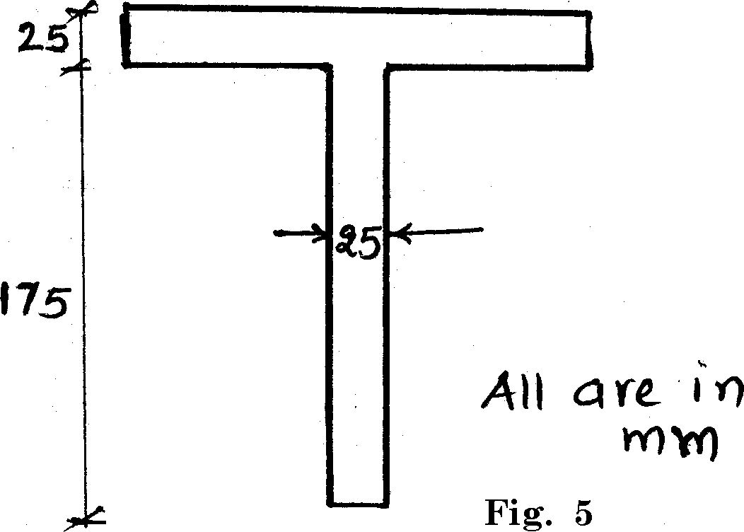
(b) A beam is supported at its two ends and induce 200 kN shear force. The cross section of the beam is shown in figure 5. Plot the shear stress distribution diagram at various point of the section. Moment of inertia (I) = 2953 x 108 mm4.
|
-at-1 2.5--* |
 |
RN-6127] 4 [ 200 ]
|
Attachment: |
| Earning: Approval pending. |