University of Pune 2009-5th Sem B.E Printing Technology T.E.(Printing) s - Question Paper
T.E. (Printing) (Semester - II) Examination, 2009
THEORY OF PRINTING MACHINIES AND MACHINE DESIGN
(2003 Course)
Illlllllllllllllllllllll [3563] - 170
Time : 4 Hours Max. Marks : 100
Instructions x I) Answer 3 questions from Section - I and 3 questions from Section - II.
P) Answers to the two Sections should be written in separate books.
3) Neat diagrams must be drawn wherever necessary.
4) Black figures to the right indicate full marks.
5) Use of electronic pocket calculator is allowed.
6) Assume suitable data, if necessary.
SECTION - I
1. a) Compare cycloidal and involute tooth forms. 6
b) Two mating involute spur gears with module of 8 mm have 23 and 57 teeth of 20 pressure angle. The addendum on pinion and gear wheel are equal to 8 mm.
Find :
i) Number of pairs of teeth in contact.
ii) Angle turned through by pinion and gear wheels.
iii) Determine sliding velocity at the beginning of contact, at pitch point and at end of contact.
The pitch line velocity is 1.2 m/s. 10
OR
2. a) State law of Gearing. 2
b) Explain interference and undercutting in involute gears. 4
c) Derive the expression for minimum number of teeth required on spur pinion to avoid interference. 10
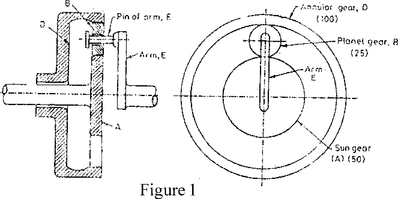
b) The sun and planet gear of an epicyclic gear as shown in Figure I. The annular gear D has 100 internal teeth, the sun gear A has 50 external teeth and planet gear B has 25 external teeth. The gear B meshes with gear D and gearA. The gear B is carried on arm E, which rotates about the centre of annular gear D. If the gear D is fixed and arm rotates at 20 rpm, then, find the speeds of gear A and B. 10
 |
|
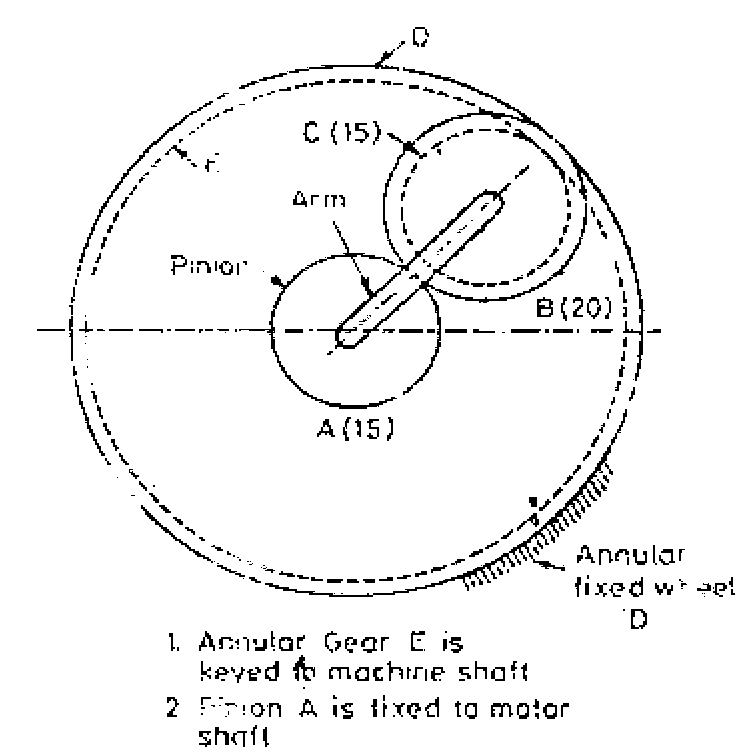
OR Figure 2 shows an epicyclic gear train. Pinion A has 15 teeth and is rigidly fixed to the motor shaft. The wheel B has 20 teeth and gears with A and also with annular fixed wheel D. Pinion C has 15 teeth and is integral with B (B,C being a compound gear wheel). Gear C meshes with annular wheel E, which is keyed to the machine shaft. The arm rotates about the same shaft on which A is fixed and carries the compound wheel B,C. If the motor runs at 1000 rpm, find the speed of machine shaft. Find the torque exerted on the machine shaft if the motor develops a torque of 100 N-m. |
16
5. a) Derive the relation for displacement, velocity and acceleration of follower of
cam performing SHM motion.
Show the variation of above three parameters with respect to cam angle for one complete rotation of cam. 6
b) Draw the profile of a cam operating a knife edge follower when the axis of the follower passes through the axis of the cam, from the following data :
i) Follower to move outwards through 40 mm during 60 rotation of cam.
ii) Follower to dwell for the next 45.
iii) Follower to return to its original position during next 90.
iv) Follower to dwell for the rest of cam rotation.
The displacement of follower is to take place with SHM during both outward and return strokes. The least radius of cam is 50 mm. If the cam rotates at 300 rpm in clockwise direction, determine the maximum velocity and acceleration of follower during the outward stroke and return stroke. 12
OR
6. From the following data, draw the profile of cam in which the follower moves with SHM during ascent while it moves with uniform accelerated and decelerated motion during descent.
|
i) |
Least radius of cam a 50 mm |
|
ii) |
Angle of Ascent a 60 |
|
iii) |
Angle of dwell between ascent and descent a 40 |
|
iv) |
Angle of descent a 60 |
|
v) |
List of follower a 40 mm. |
|
vi) |
Diameter of roller a 30 mm. |
|
vii) |
Distance between line of action of follower and axis of cam a 20 mm. |
If the cam rotates at 360 rpm in clockwise direction, find the maximum velocity and acceleration of follower during descent. 18
SECTION - II
7. a) i) Define stress concentration.
ii) Explain the causes of stress concentration.
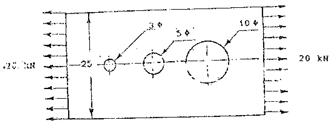
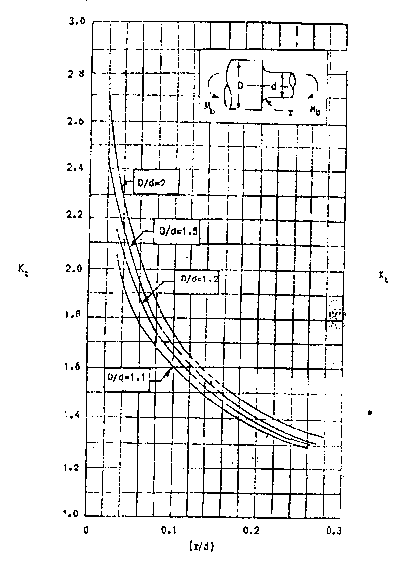
b) A rectangular plate, 15 mm thick, made of a brittle material as shown in F igure 3. Calculate the stresses at each of the 3 holes of 3, 5 and 10 mm diameter respectively. Refer Figure 4 for related data. 9
 |
|
Figure 3 |

i) Surface finish factor
ii) Size factor
iii) Reliability factor
iv) Modifying factor to account stress concentration.
8
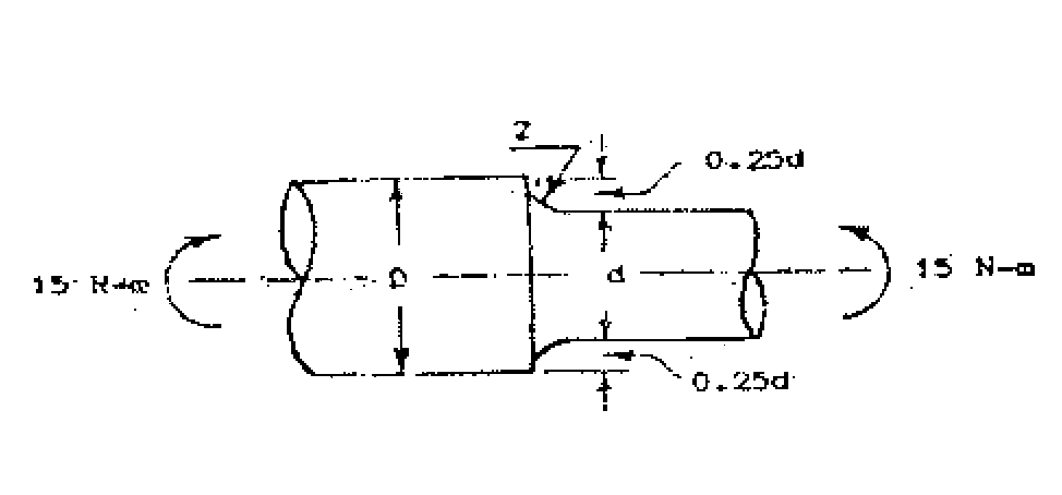
b) A round shaft made of brittle material and subjected to a bending moment of 15 N-m as shown in Figure 5. The stress concentration factor at the fillet is 1.5 and ulimate tensile strength of the material is 200 N/mm2. Determine the diameter d, the magnitude of stress at fillet and the factor of safety. Refer Figure 6 for related data. 8
 |
|
Figure 5 |
9. A spur pinion having 21 teeth is to be made of plain carbon steel 55C8 (Sut a 720 N/mm2) is to mesh with a gear to be made of plain carbon steel 40 C8 (Sut a 580 N/mm2). The gear pair is to transmit 22 kW power from an IC engine running at 1000 rpm to a machine running at 300 rpm. The starting torque required is 200% of the rated torque, while the load distribution factor is 1.5. The factor safety required is 1.5. The face width is ten times the module and the tooth system is 20 full depth involute. The gears are to be machined to meet the specification of grade 6. The gear and pinion are to be case hardened to 400 BHN and 450 BHN respectively. The Deformation factor C for gear pair is 11500 e, N/mm. Design
the gear pair by using dynamic factor dynamic load. Use following relations :
and Buckinghams equation for
(6+V)
2.87 Dynamic load _ 21V(bC+Ftmax)
Y= 0.484-
K = 0.16
Z D (F<i) " 21V+VbC+Ftmax
R = K K R
J-tmax -LVm-1
Q a
For Grade 6 : e a 8.0 + 0.63 <|>p (microns)
(|)p=m+0.25Vd - (tolerance factor)
All notations have usual meanings. OR
b) The following data is given for a steel spur gear pair transmitting 5 KW power from shaft rotating at 1500 rpm.
Module a 4 mm
i
ii
iii
iv
v
vi
vii
viii
ix
x
Service factor @Ka) and load distribution factor @Km) a 1 Number of teeth on pinion a 18
Allowable bending stress for pinion and gear a 210 N/mm2.
Face width a 40 mm.
Surface Hardness a 400 BHN Tooth system a 20 full depth involute Combined teeth error @e) a 15 microns Deformation factor C a 11400 c, N/mm Buckinghams equation for dynamic load
F,=
,N
Z
BHN
100
K a 0.16
, F
21V+-N/bC+Ftr 2.87
_ 21V(bC+Ftmax)
t a K . K . Ft
tmax a m t
xi) Y a 0.484 -
f DU\T \2
Assuming the dynamic load is accounted by Buckinghams equation, calculate :
i) The factor of safety against bending failure.
ii) The factor of safety against pitting failure.
10
8
11. a) Compare ball and roller contact bearings.
b) A 22 kW, 1440 rpm electric motor is directly coupled to a shaft of 25 mm diameter, which is supported by two cylindrical roller bearings. The shaft transmits power to another line shaft through a flat pulley of 300 mm diameter which is placed mid-way between the two bearings. The coefficient of friction between the belt and pulley is 0.3, while angle of lap is 180. The belt is horizontal. The load factor is 1.5. If the expected life of bearing is 50,000 hrs, select the bearing from manufacturers catalogue. Use the following data :
|
Bearing No |
NU 2205 |
NU 2305 |
|
Basic Dynamic Capacity 'C' (kN) |
15.99 |
31.39 |
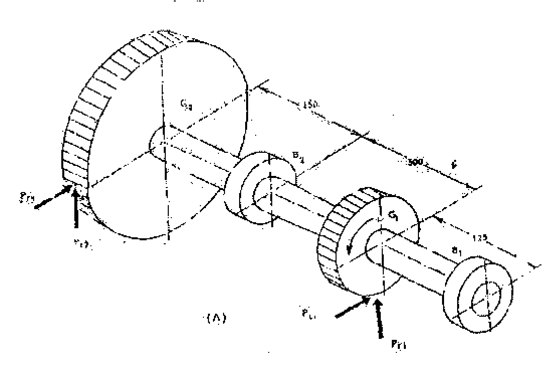
12. A shaft transmitting 50 kW at 125 rpm from G1 to gear G2 and mounted on two single row deep groove ball bearings B1 and B2 as shown in Figure 7. The gear tooth forces are
Pt a 15915 n P a 5793 n
t1 r1
Pt a 9549 N P a 3476 n
t2 r2
The diameter of the shaft at bearings B1 and B2 is 75 mm. The load factor is 1.4 and the expected life for 90% of bearing is 10,000 hrs. Select a suitable ball bearing.
Refer F igure 8 for related data. 16
 |
|
Figure 7 |
|
Principal dimensions (rtinV) |
Uasic !u;id iu lings (N) |
Design;: tic | ||
|
d D |
jj |
c | ||
|
75 95 |
10 |
9S00 |
61815 | |
|
IIS |
l? |
2S600 |
<W>00 |
106! 5 |
|
US |
20 |
3.9700 |
26000 |
6015 |
|
130 |
6(K> |
iftSOD |
6215 | |
|
160 |
.37 |
112000 |
72000 |
6335 |
|
. ,iyo |
4S |
153000 |
114000 |
6115 |
Figure 8
Time : 3 Hours Max. Marks : 100
Instructions : I) All questions are compulsory.
2) Answers to the two Sections should be written in separate books.
3) Neat diagrams must be drawn wherever necessary.
4) Black figures to the right indicate full marks.
SECTION - I
1. Explain Human Vision Mechanism with neat diagram. 8
2. Explain the term Colour Temperature. Explain two standard illuminants used in colour measurement with their colour temperature and spectral power distribution graph. 8
OR
1. Explain Additive and Substractive colour theory used in colour reproduction with neat diagram. 8
2. Write down the three attributes of colour. Explain them by considering Munsell colour system. 8
3. Write down the name of different types of instruments used for colour measurement. Explain the basic principle of reflection and transmission densitometer with neat diagram. 8
4. Explain CIE XYY space with diagram. 8
OR
3. Explain the basic principle of spectrophotometer with diagram. 8
4. Answer any two : 8
a) Trapping
b) Hue error and greyness
c) Gray balance
5. Explain any three : 12
a) Three Cs of Colour Management.
b) Test charts used for the different profiles.
c) Explain Custom, Generic and Process profile.
d) CIE Lab
e) Look up table
6. What is Colour Management ? Why it is required ? 6
OR
6. What is device profile ? Explain Input profile in detail. 6
SECTION - II
7. Explain Device independent and Device dependent workflow. 8
8. What is output Profile ? How it is developed ? 8
OR
7. What is the use of rendering intents while developing profile. Explain perceptual
and saturation intent with neat diagram. 8
8. What is gamut ? Explain the gamut of different device with neat diagram. 8
10. Explain the digital soft proofing and hard copy proofing with their one advantage
and one disadvantage. 8
OR
9. Explain non-colour managed workflow and colour managed workflow with neat
diagram. 8
10. Explain colour management in photoshop. 8
11. Solve any two : 12
a) Explain Flat bed scanner with neat diagram.
b) Write down the name of different types of imagesetter used in colour reproduction. Explain any one in detail.
c) Compare digital printing with conventional printing.
12. Explain any three : 6
a) Digital Camera resolution.
b) Bit depth (Grey levels).
c) Lens focal length.
d) Iris diaphragm.
e) Filters.
Time : 3 Hours Max. Marks : 100
Instructions : I) Answers to the two Sections should be written in separate books.
P) Neat diagrams must be drawn wherever necessary.
3) All questions are compulsory.
SECTION - I
1. Answer the following in brief (any four) : 16
a) Why is the clearance between blanket and impression cylinders adjustable ?
b) What tool is used to accurately measure the thickness of a blanket and plate ?
c) How does a Lithographic plate work ?
d) Why do plate and blanket cylinders in sheetfed lithography have gaps ?
e) What is meant by packing to bearer height ?
OR
1. a) Explain with a neat labelled sketch, working procedure of automatic plate loading
(APL) system on sheetfed offset press. 10
b) Compare APL with manual mounting. 6
2. State whether following statements are True or False and why ? 16
a) Ink form rollers have more ink where the plate has more ink.
b) Ink rollers become glazed due to fountain solution and gum arabic.
c) Inks used in offset lithography are more tackier.
d) Ink form roller to plate pressure is checked by paper strip method.
OR
2. Assume you are deciding upon which press to buy. What specific things will you look for when judging the inking system of a press. Include atleast 4 things. 16
b) Explain what a fountain solution recirculation device is used for. 3
c) List atleast 3 things that are likely to happen if the pH number of the fountain solution is too low. 6
OR
3. a) List three of the main problems with conventional dampening system and how
nonconventional systems solve the problems. 9
b) Explain in what way can the term emulsification be applied to the inking and/or dampening system ? 3
c) Write short note on Turbo Dampening system. 6
SECTION - II
4. Write short notes on : 16
a) Successive (single) sheet feeder.
b) Pile height governor.
c) Double sheet detector.
d) Swing grippers.
OR
4. With the help of detailed diagrams explain 3 point register system. 16
5. Answer the following :
a) How can proper space allocation and equipment location help increase a press crews productivity ? 4
b) Why is proper scheduling an important aspect of premakeready ? 6
c) When does makeready start and end for a print job ? 6
OR
5. Explain the following problems related to press. 16
a) Dot gain
b) Slur
c) Doubling
6. a) How can you identify the warp direction of blanket ? 4
b) Of what significance is the warp direction when installing a blanket ? 4
c) Explain any 3 performance requirements of a blanket. 10
OR
6. a) The primary objective of a preventive maintenance programme is to keep
equipment in top operating condition and to prevent breakdown. Explain in short. 6
b) Explain daily and weekly maintenance checklist for single colour offset press. 12
T.E. Printing (Semester - II) Examination, 2009 SURFACE PREPARATION - I (2003 Course)
Time : 3 Hours Marks : 100
Instructions x I) All questions are compulsory.
2) Answers to the two Sections should be written in separate books.
3) Neat diagrams must be drawn wherever necessary.
4) Black figures to the right indicate full marks.
SECTION - I
1. A) Explain any two factors to be considered while deciding the layout of the plate
making department in brief with suitable examples. 8
OR
1. A) Explain the workflow of traditional/conventional plate making department. 8
B) Explain the role of machine size and job size in deciding the imposition scheme with suitable examples and diagrams. 8
2. A) Differentiate between Water Deep Etch and Gum Deep Etch Plate with minimum
four points. 8
B) Explain the response of positive and negative PS plates towards exposure with suitable diagrams. 8
OR
2. A) State the advantages and limitations of Deep Etch Plate making method over
Pre Sensitized Plate making method. 8
B) Explain the construction of automatic plate processor used to process PS plates with suitable diagram. 8
3. A) Explain the advantages and limitations of Drio-graphic printing process over conventional lithographic printing process.
B) Differentiate between Reflection and Projection type of diffusion transfer plate making method.
OR
3. A) Explain the advantages and limitations between Direct and Indirect
Electrophotostatic plate making method.
B) Explain in brief the Regilon and Miraclon Type of Water soluble photosensitive resin plate making method.
SECTION - II
4. A) Explain the benefits and drawbacks of CTP system.
B) Explain any two technologies of CTP system with suitable diagram :
i) Flat bed CTP.
ii) Internal drum CTP.
iii) External drum CTP.
OR
4. A) Explain the Write white and Write black type of CTP Technology and state
its relationship with Positive working and Negative working type of CTP technology.
B) Explain various components of the CTP system.
5. A) Why Indirect Photographic method of screen making technique is used for the
printing of high resolution image areas only ? Explain with suitable examples and diagrams.
B) Differentiate between Multifilament and Monofilament fiber structure with diagram and suitable example.
OR
5. A) Explain the reason of exposing the Indirect Photographic film from non emulsion side with suitable diagrams.
B) Differentiate between Nylon and Polyester mesh.
6. A) Write short note on (any three) :
i) Temperature and Relative Humidity.
ii) Room Lighting.
iii) Use of colors on wall and ceiling.
iv) Waste disposal.
v) Flooring.
B) Find out the total cost of plate making for the given job :
Demy 1/4 size 36 (Black and White)
Annual Magazine
Text Pages
Cover
Machine
Quantity
PS Plate
Pasting
CTP
OR
4 Pages (4 Colour)
18x 23
1000 Nos.
18 x 23 Cost : Rs. 125/- each 18 x 23 Cost : Rs. 35/- each 18 x 23 Cost : Rs. 800/- for one set
6. A) Write short note on (any2three) :
i) Continuous tone wedge.
ii) Microline patches.
iii) Halftone wedge.
iv) Slur and Doubling Target.
v) Small dot patches.
B) Suggest the suitable plan, plate wise/form wise for printing the given job in tabular format with suitable diagrams wherever necessary :
Demy 1/4 size 36 (Black and White)
Annual Magazine Text Pages Cover Machine Quantity
4 Pages (4 Colour) 18 x 23
1000 Nos.
Time : 3 Hours Max. Marks : 100
Instructions: I) Answers to the two Sections should be written in separate books.
2) Neat diagrams must be drawn wherever necessary.
3) Black figures to the right indicate full marks.
SECTION - I
1. a) Explain different data transfer techniques. 8
b) Explain basic problems of long distance transmission. 8 OR
2. a) Explain various data networks. 8
b) Explain data transfer using satellite network. 8
3. a) What is modulation ? Explain pulse position modulation with suitable diagram. 8
b) What is multiplexing ? Explain time division multiplexing with block diagram. 8 OR
4. a) What is quantization ? Explain uniform and non uniform quantization. 8
b) Explain companding with 'A' law and V' law with suitable diagram. 8
5. a) What are various types transmission channels ? What is channel capacity ? 8
b) Explain different types of noise. 10
OR
6. Write short notes on (any three) : 18
1) Data Transfer using E-mail
2) Image grabbing and transfer
3) Tele text
4) Videotex
5) Noise interference and remedies.
7. a) What are different types of light sources ? Explain LED. 8 b) Explain laser printer application. 8
OR
8. a) Explain sheet thickness measurement with magnetic and optical sensors. 8 b) What are different photo detectors ? Explain characteristic of photo-diode. 8
9. a) Explain the construction and working of fiber optic cable. 8
b) Explain the different losses in fiber. 8 OR
10. a) Explain with block diagram basic fiber optic communication system. 8 b) Derive the expression for numerical aperture of optical fiber. 8
11. a) Explain plate making application using laser. 10
b) What is RFID ? Explain with one application. 8 OR
12. a) Explain Wi-Fi technology. 10 b) Explain smart ticket application of RFID. 8
T.E. (Printing) (Semester - I) Examination, 2009 DESIGN OF PRINTING MACHINE COMPONENTS (2003 Course)
Time : 3 Hours Max. Marks : 100
Instructions x I) Answer any three questions from each Sections.
2) Figures to the right indicate full marks.
3) Use of calculator is allowed.
4) Assume suitable data, if necessary.
SECTION - I
1. a) State and explain the significance of service factor and overload factor. 6
b) A shaft supported on two bearings at the end carries the load of 10,000 N at the middle of shaft. The length of shaft is 150 mm. The power is transmitted to the shaft by gear drive. The power transmitted is 10 kW at 1440 rpm. The material used for shaft has ultimate tensile strength of 620 N/mm2 and yield strength 480 N/mm2. The factor of safety is 1.5. Design the shaft using ASME code. 10
OR
a) Explain creativity in design and explain step by step procedure for design of shaft on basis of ASME code. 10
b) Explain importance of geometric tolerance and method to specify them on machine component drawing. 6
2. a) Explain limit, fits in the machine elements. What are different types of tolerances.
Show how to give such tolerance of machine elements ? 8
b) Draw neat sketch of cotter joint. Also explain design of cotter joint. 8
OR
a) What are important considerations in selection of material in design. 8
b) Design a cotter joint to transmit a load of 90 kN in tension or compression. Assume following stress for socket, spigot and cotter.
Allowable tensile stress a 90 MPa
Allowable crushing stress a 120 MPa
Allowable shear stress a 60 MPa 8
3. Write short notes (any three) :
1) Types of fit
2) Different methods to make bolt of uniform strength
3) Design of shaft by rigidity approach
4) Knuckle joint.
SECTION - II
4. a) Explain important factor in selecting a coupling.
b) Design a clamp coupling to transmit 30 kW at 100 rpm. The allowable shear stress and crushing stress for shaft and key is 34 N/mm2 and 70 N/mm2 and the number of bolts connecting the two halves are size. The permissible tensile stress for bolt is 70 N/mm2. The coefficient of friction between muff and shaft surface may be taken as 0.3 for cast iron allowable shear stress may be taken as
15 N/mm2.
c) For a square key equally string in shear and crushing show that crushing stress a 2*shear stress.
OR
4. a) Prove that maximum efficiency of square threads is given by
1-sin 6
a) max _ , r*
1 1 + sin 0
where is pressure angle. b) What are the different types of stresses induced in power screw ?
5. a) Design a helical compression spring for maximum load of 1000 N for deflection
of 25 mm using value of spring index as 5.
b) Explain spring nomenclature.
OR
5. a) Derive load deflection equation of Helical spring. b) Derive local stress equation of Helical spring.
6. Write short notes (any three) :
a) Derive the relation for torque required to raise the load on square threaded screw
b) Types of keys
c) Mounting methods of bearings
d) Static and dynamic load carring capacity of bearings.
Time : 3 Hours Max. Marks : 100
Instructions x I) Answer 3 questions from Section I and 3 questions from Section II.
2) Answers to the two Sections should be written in separate books.
3) Neat diagrams must be drawn wherever necessary.
4) Black figures to the right indicate full marks.
5) Use of logarithmic tables, slide rule, Mollier charts, electronic pocket calculator and steam tables is allowed.
6) Assume suitable data, if necessary.
7) Solve Q. 1 or Q. 2, Q. 3 or Q. 4, Q. 5 or Q. 6 from Section I and solve Q. 7 or Q. 8, Q. 9 or Q. 10, Q. II or Q. 12 from Section II.
SECTION - I
1. a) Define the term measurement. Explain the block diagram of generalized
measurement system. 8
b) With suitable example explain the term servomechanism. 8
OR
2. a) Explain the following terms :
i) Threshold
ii) Resolution
iii) Linearity
iv) Drift 8
b) Explain the different types of errors. Explain the suitable methods to minimize these errors. 8
3. a) Define the term transducer. Explain the factors on which transducer selection
depends. An instrument converts linearly 0-300m3/sec. flow rate to a 4-20 mA. current signal. Calculate the current for 225m3/sec. flow rate. 8
P.T.O.
Suggest suitable transducer for following measurements. Justify your selection.
i) Temperature of furnace a 0-1700C.
b)
ii) Pressure in pressure cooker
iii) Measurement of water level in dam
iv) Air flow measurement. 8
OR
Explain in detail potentiometric type accelerometer. 8
4. a) b)
5. a) b)
6. a) b)
Explain in detail toothed rotor variable reluctance type tachometer. 8
Explain the term LDR. Explain role of optodevices in printing applications. 8
Explain the terms CMRR and slew rate. Draw and explain inverting amplifier configuration and derive its gain. 10
OR
Explain in detail sample and hold circuit. 8
Explain in detail InstrumentationAmplifier using three op-amps. Derive the equation for its overall gain. 10
SECTION - II
What is automatic control ? Explain different process characteristics. 8
7. a) b)
8. a) b)
Explain Bang-Bang control in detail. 8
OR
Explain in detail final control operation for any one industrial parameter. 8
List the different single mode controller. Can we use single mode controllers alone ? Justify. 8
9. a) Draw and explain electropneumatic converter. 8
b) Explain with neat sketch pneumatic P+I controller. 8 OR
10. a) Explain with neat sketch electronic PID controller. 8 b) Explain role of microprocessor in different printing applications. 8
11. a) Define the term PLC. Draw and explain the architecture of PLC. 8
b) What are the advantages of PLC over relay logic controller ? Which are the languages
used for PLC programming ? Which inputs and outputs are accepted for PLC ? 10
OR
12. a) Explain in detail SCADA system. 8
b) Why data loggers are used in systems ? Explain with block diagram multichannel
data logger system. 10
T.E. (Printing) (Semester - I) Examination, 2009 (2003 Course) PRINTING NETWORK AND COMPUTER GRAPHICS
Time : 3 Hours Max. Marks : 100
Instructions : I) Answer Q. 1 or Q. 2, Q. 3 or Q. 4, Q. 5 or Q. 6/Q. 7 or Q. 8, Q. 9 or Q. 10, Q. 11 or Q. 12 questions from each Section.
P) Answers to the two Sections should be written in separate books.
3) Neat diagrams must be drawn wherever necessary.
4) Black figures to the right indicate full marks.
5) Use of logarithmic tables, slide rule, Mollier charts, electronic pocket calculator and steam tables is allowed.
6) Assume suitable data, if necessary.
SECTION - I
1. Explain DOS with the help of following points : 16
A) Features.
B) DOS structures.
C) Boot up sequence.
D) Internal and external DOS commands with sequence.
OR
2. a) Explain UNIX operating system. 8
b) Explain the features of WINDOWS operating system. Differentiate between DOS and WINDOWS operating system. 8
3. a) Classify and explain different network types. 10
b) What is the role of internet in Printing Industry ? 8
OR
4. a) Explain the OSI reference model. 10 b) Explain the IP Protocol in detail. 8
5. a) Explain the basic graphics system. 8
b) Explain the TIFF file format. 8 OR
6. a) Explain the Video RAM. 8 b) Explain the fundamental steps involved in image Processing. 8
SECTION - II
7. a) What is internetworking ? Explain different internetworking devices. 8
b) Explain VSAT and its application in Printing field. 8
OR
8. a) What is ISDN ? State different services offered by ISDN. Explain any one
service in detail. 8
b) Explain video conferencing in detail. 8
9. a) What is workflow ? Explain the features of workflow system. Explain the
application of workflow system in newspaper industry. 10
b) Explain the integration of prepress-press-postpress. 8
OR
10. a) What is DBMS ? What are the applications of DBMS in Printing Industry ?
Explain the three level architecture of DBMS. 10
b) Explain PDF Workflow system. 8
11. a) What are input devices ? Explain different Input devices and its application in
Printing. 16
OR
12. a) What are output devices ? Explain different output devices and its application in
Printing. 16
B/I/09/J20
|
Attachment: |
| Earning: Approval pending. |