Indian Institute of Technology Kharagpur (IIT-K) 2008 B.Tech Basic electronics - Question Paper
INDIAN INSTITUTE OF TECHNOLOGY
DaW...i...~ ..?P.n?..?r..?P08FN/AN Time : 2j Hrs. Full Marks ........... No. of Students
ol L'ClODt
Autumn Semester..........Sub.No.
2rtd YearF
BASIC ELECTRONICS
r B,Tech. (Hj /' J/M.Sc. Sub. Name
1 Instruction ANSWER ALL QUESTIONS. All Symbols have their usual meaning
All necessary derivations should be shown clearly.
Mark will be given as per steps shown.
Q.1 In the following indicate the correct/best answer. Show necessary derivations. Mark will be given as per steps shown in the derivations,
j/) The voltage Vi across the 6Q resistor is (i) 6V, (ii) 3.5V, (iii) 12V, (iv) 8V, (v) 3V
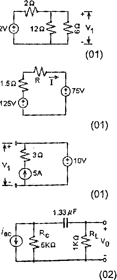
(b) In the adjacent circuit if the current I is not to exceed 5A, the minimum resistance R will be
(i) 100, (ii) 50, (iii) 38.50, (jv) 8.5Q
(c) The voltage Vi in the adjacent figure is
(i) 20V, pi) 15V, (iii) 10V, (iv) 5V
(d) The 3 dB cutoff frequency for this circuit is
(i) Low pass, 20 Hz, (ti) high pass, 20 Hz,
(iii) low pass, 120 Hz, (iv) high pass, 120 Hz, (v) low pass, 143.5Hz, (vi) high pass,143.5 Hz
(e) The input to an amplifier is 2mW and the amplifier output is 20mW. Then the gain of the amplifier fn decibels is
(i) -20 dB; (ii) -10 dB; (iii)+3 dB ; (iv) +10 dB, (yf+20 dB
(01)
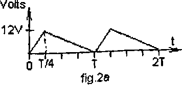
fig.2b
Q.2 (a) A triangular wave is shown in fig.2a. Show that the rms voltage of this waveform is 12/V3 volts. USW
(b) The waveform in fig.2a is passed through a series capacitor, which removes its dc level so that it appears as shown in fig.2b. Find the rms voltage of this resulting waveform. < ,,
P.T.O.
(06)
Q.3 (?) Design a filter with 1 KQ resistors and 0.1 p.F capacitors to give the response shown in fig.3a. Determine its 3 dB cutoff frequency fo.
The voltage regulator shown in fig ,3b Rs i has a Zener diode with a ON voltage ol 20V. It is NNirnf used to regulate the voltage across the toad x 1
resistor Rl at 20V. The input voltage is V\n=30V \
and Rl=1KQ. For Rs you have. available \wo -L
resistors (100Q and 1000Q). Which will you rb
choose? Justify by calculations.
(06)
12K 4V,
rNM*-1


Q.4 (a) A sinusoidal input voltage v-, varying between +8V to -8V is applied to the circuit shown in fig.4a . Sketch the output v0 in relation to the input v-,. Mark the necessary voltage levels.
(b) A square wave input voltage Vj varying between +8V to -8V is applied to the circuit shown in fig ,4b below. Assume that the time constant RC T. Sketch the output Vo in relation to the signals %


(a) A fixed bias circuit using a S\ transistor is shown in fig.5a. Determine Ib, 1c> Vce, Vc, Ve, VBl VBc. Determine the region ol operation of the transistor.

Jb) In fig.5b. Determine 1B, lc,
Vce, Vc. Ve, Vb, VBc. Determine the region q_\i of operation of the transistor. 11 R
-No
1 AV
|
Attachment: |
| Earning: Approval pending. |