Indian Institute of Technology Kharagpur %28IIT-K%29 2010 B.Tech Mechanical Engineering Mechanics - Question Paper
INDIAN INSTITUTE OF TECHNOLOGY, Kharagpur
Date: / /2010 FN/AN End semester(Autumn) 2010 Time:3 hrs Full Marks: 100
Dept: first yr B.tech/B.arch/Int. M.Sc/DD Subject Name: Mechanics Subject No: ME10001
All ques. carry equal marks(20 X 5).Marks distribution for every ques. is indicated within brackets.
presume any suitable data that may be needed for solution, stating clear justifications
Summary: This exam is conducted in the name of basic engineering to every Undergraduate learner who entered IIT on the basis of JEE
INDIAN INSTITUTE OF TECHNOLOGY, Kharagpur Date: I /2010 FN/AN End Semester (Autumn) 2010 Time: 3 hrs Full Marks: 100 Dept.: 1st yr B.tech. / B.arch /Int. M. Sc./DD Subject Name: Mechanics Subject No.: ME10001
All questions carry equal marks (20 X 5). Marks distribution for each question is indicated within brackets. Assume any suitable data that may be requiredfor solution, stating clear justifications.
Question paper has 2 pages. Answer all questions.
|
(1) A riveted butt joint shown in Figure 1 is subjected to uniformly distributed load of 392.7 N/mm. Plate thickness is 15 mm and the rivet spacing is 100 mm. Factor of safety is 2.5. Allowable shear stress for rivet is 100 MPa. Allowable tensile stress for the plate is 140 MPa. Allowable bearing stress is 300 MPa. Find the rivet diameter. Check for bearing failure and the tearing of the plate between the rivet holes. Suggest minimum thickness for the cover plates. |
IS mm XT?-
|
Figure 1
Fixed
Support
12.5 kN/m
20 kN
A/3Z$_$Z3_t
B
/I
2m
3m
'lm
(2)
(a) Draw the shear force and bending moment diagrams for the straight portion of the beam (AB) with all the critical ordinates. Furnish all the supporting calculations. Refer to Figure 2a.
(10)
|
(b) Derive the equation of the elastic line of the segment AB of the bent beam ABCD, with Youngs modulus E and moment of inertia I, loaded as shown in Figure 2b. End A is fixed. Find the vertical deflections of points B andD. |
| ||||||||||||||||||
|
Figure 2b |
 |
|
View from the right |
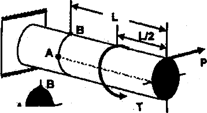
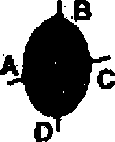
(a) A steel shaft of diameter 20 mm, as shown, is subjected to a torsion, T = 20 N-m and a force, P = 500 N, acting parallel to the diameter as shown in the Figure 3a. Find the state of stress at the locations A, B, C, D lying on a vertical cross section which is at a distance of L = 100 mm from the free end of the shaft. Give the sketches of the stress elements.
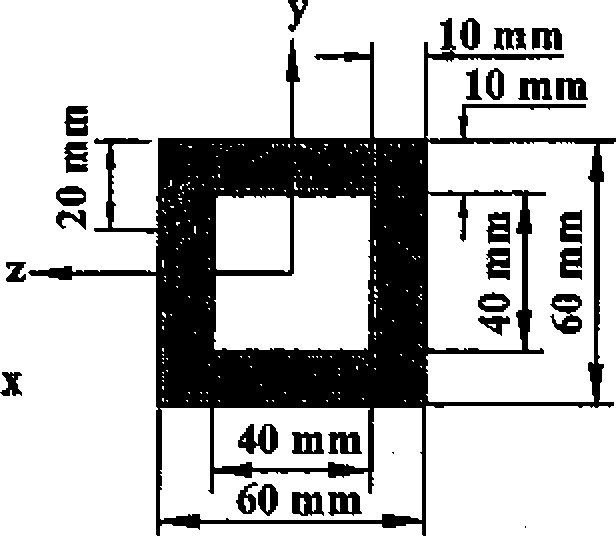
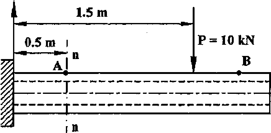
(b) A cantilever beam is loaded as shown in Figure 3b. Compute the bending stress at the point A and the shear stress (Txy) at the point C located as shown in the transverse cross-section at n-n. (b)
Determine the bending stress at the point B.
 |
|
Section at n-n |
 |
\ Strain Gage |
|
Figure 4 | |
 |
|
Figure 3 b |
(4) A long closed thin cylindrical vessel with wall thickness, /, having an internal radius R is internally pressurized to a gage pressure p. If a strain of 10"3 is recorded by a gauge at 30 to the axis of the cylinder, as shown in Figure 4, calculate (a) the pressure p and
(b) the percentage change in the radius of the container at the axial location of the strain gage. Take Youngs modulus as E and Poissons ratio as u.
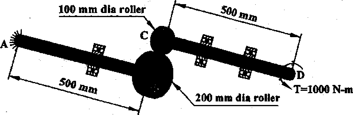
(5) The torque T is to be transmitted through the roller-shaft system without slippage between the rollers, as shown in Figure 5. The shafts AB and CD are of equal diameter and made of steel (G=70
GPa). If the angle of twist at the end D of the shaft CD is 1.5 then determine the diameter of the shafts and the maximum value of the shear stress in the shaft AB. End A is fixed.
 |
|
Figure 5 |
|
Attachment: |
| Earning: Approval pending. |