Indian Institute of Technology Kharagpur %28IIT-K%29 2010 B.Tech Electrical Engineering Electrical technology - Question Paper
INDIAN INSTITUTE OF TECHNOLOGY, KHARAGPUR
Department of Electrical Engineering
End semester exam for Electrical Technology (EE11001)
Date:26,November 2010,9AM to 12noon
Time:3 hours Full Marks: 100
ans any five ques.. Make assumptions if needed and state them clearly. This paper has two pages
Summary: This exam is conducted in the name of basic engineering to every Undergraduate learner who entered IIT on the basis of JEE
INDIAN INSTITUTE OF TECHNOLOGY KHARAGPUR Department of Electrical Engineering
End-Semester Examination for Electrical Technology (EE11001)
Date: 26, November 2010, 9AM to 12 Noon Time: 3 hours Full Marks 100
Answer any 5 questions. Make assumptions if needed and state than clearly. This paper has 2 pages.
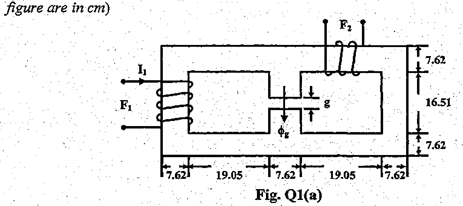
1. (a) In the magnetic circuit shown in Fig. Qi(a) the coil Fj is supplied with 350 ampere-tirms in the direction indicated. Find the direction and magnitude of the mmf required in coil F2 for the air-gap flux to be 1.8 mili Wb. The core has an effective cross-sectional area of 58.06 cm2 throughout and a relative permeability of 4000. The length of the air gap is 0.127 cms. (all dimensions in the
(b) When two mutually coupled coils are connected in parallel, derive the total equivalent inductance when(i) the flux of coils are adding and (ii) also when the flux of the coils are opposing. [8]
2. The following data were obtained from testing a 48kVA, 4800/240V, 50Hz transformer.
Open circuit test (HV side open) 240V, 2A, 120 watts
Short circuit test (LV side short circuited) -* 150V, 10A, 600 watts.
Calculate
(a) the input voltage and the input power when the transformer is loaded with a capacitor and delivering full load current at 240 V. [8+2]
(b) the highest efficiency of the transformer, the corresponding kVA output and power factor. [4+2]
(c) all-day efficiency of the transformer, when it is connected to a substation delivering 20kW at 0.8 power factor (lagging) from 6AM to 6PM and 40kW at unity power factor for rest of the period of a day. [4]
3. (a) Show that a balanced 3-phase distributed winding produces a constant magnitude rotating
magnetic field. Comment on its speed and direction of rotation. [5]
(b) A 3-phase, 400V, 50Hz, 4 pole induction motor with stator and rotor star connected, has per phase rotor resistance of 0.30 and stand still reactance of 1.00. Ratio of stator to rotor turns is 1.25. If the full load slip is 4%, calculate the (i) torque developed (ii) power developed at the rotor (iii) ratio of starting torque to maximum torque (iv) the extra resistance to be connected in each rotor phase so as to make starting torque equal to 75% of maximum torque. [3+2+5+5]
4. (a) A 220V dc shunt motor takes 20A at rated voltage and runs at lOOOrpm. Its field resistance is
110O and armature circuit resistance is 0.10. Compute the value of additional resistance required in the armature circuit to reduce the speed to 800rpm when the load torque varies as the square of the speed. [10]
(b) A 250V shunt motor has an armature resistance of 0.60 and a field resistance of 2500. When driving at 650rpm, at constant torque load, the armature takes 20A. If it is required to raise the speed from 650rpm to 850rpm, what resistance must be inserted in the shunt field circuit? Assume linear magnetizing characteristic. [10]
5. (a) Derive the relation for the ratio of weight of copper requirement for windings of an
autotransformer and that to a two-winding transformer for the same voltage ratio and VA rating. Given, the primary to secondary voltage ratio is less than one. . [6]
(ii) A load is to be supplied through a transformer of rating 50 kVA, 400/460 V, 50 Hz. If an autotransformer will be used for the purpose, what percentage of copper will be saved compared to a two-winding transformer? [4]
(b) "What are the problems of starting for a 3-phase cage-type induction motor with Ml voltage? [3] With tile help of circuit diagrams compare the starting currents drawn from the supply and the starting torque developed by a 3-phase induction motor for (i) direct-on-lme(full voltage starting) (ii) autotransformer starting. [7]
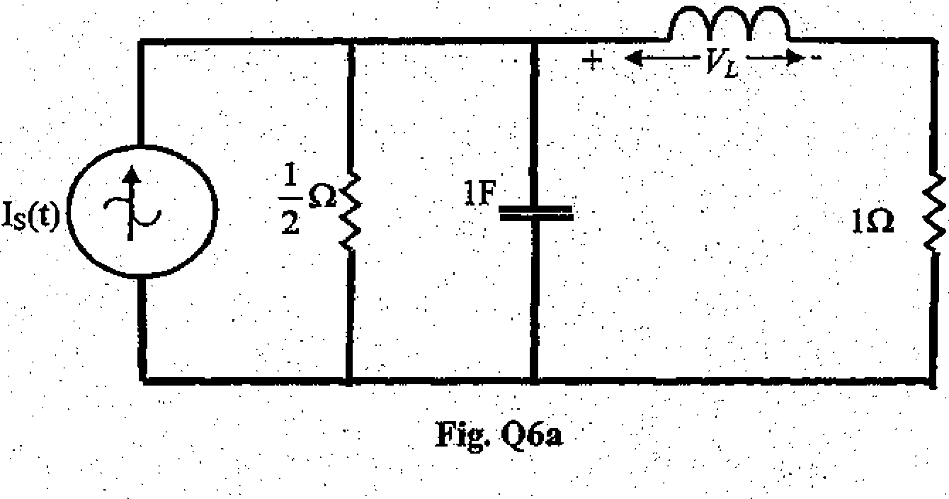
6. (a) In the circuit shown in Fig. Q6a, the voltage across the inductor, VL (f) ~-2 cos 2t volts.
(i) Obtain the current and voltage phasors in all the elements and the current supplied by the current source.
(ii) Calculate the power absorbed by all the elements and show that their sum is equal to the power delivered by the current source.
(iii) Draw the phasor diagram for the currents and voltages in the circuit. [5+2+3]
A 3-phase, 50Hz, 400V system feeds a load of 25 kW at a power factor of 0.7 lagging as shown in Fig. Q6b. Three capacitors are connected across the load as shown to improve the power factor to 0.85 lagging. Determine the value of the capacitance C\ current drawn from the supply (Is), current Ic in the capacitor and current II flowing into the load. [10]
(b)
|
400 V, 50 Hz 3-phase supply | 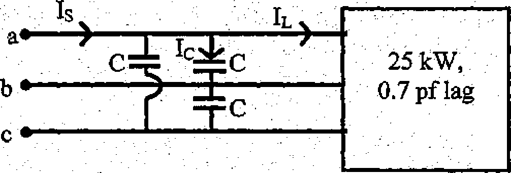 |
fg. Q6b
End of the question paper
|
Attachment: |
| Earning: Approval pending. |