Thapar University 2006 B.E Electronic Instrumentation & Control Engineer Solid Mechanics - Question Paper
Thapar Institute of Engineering & Technology
B.Tech Electrical & Instrumentation (1st Year)
Final Term exam
ES102 (Solid Mechanics)
T HAP AR INSTITUTE OF ENGINEERING AND TECHNOLOGY: PATIALA END SEMESTER EXAMNIATION SEMESTER: I SESSION 2006-2007
ES-102 SOLID MECHANICS
(
M.WWKS:t00_MME: 3.00XOVty
Note: Attempt five questions in all
Symbols have their usual meanings
WRITE YOUR GROUP NUMBER ON THE FIRST PAGE OF THE ANSWER SHEET
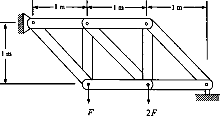
Q.l. Determine the safest value of F on the truss shown in Figure 1 assuming that each member is capable of supporting a tensile load of 28 kN and a compressive load of 12 kN safely.
 |
|
Figure 1 (20) |
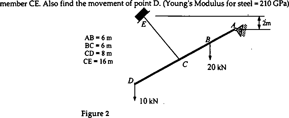
Q.2. In the structure shown in Figure 2, member ABCD is a rigid member pinned to the wall at A, and supported by steel cable CE of 25 mm diameter. The inclinations of cable CE and bar ABCD are 30 and 37 respectively from horizontal. Determine the axial stress, the deformation and the strain in
Q3 A circular rod is subjected to combined bending and twisting moments of 10 kNjn and 30 kN.m respectively. Assuming Sy, = 235 MPa, = 120 MPa and factor of safety of 3, determine the shaft
diameters) assuming the rod to be
(a) solid and only bending moment is acting,
(b) hollow with rimer = 0.35 and only twisting moment is acting,
(c) solid and using maximum shear stress theory
(d) solid and using maximum distortion energy theory
(04,04,06, 06)
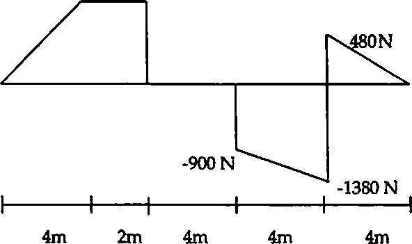
Q.4 Draw the load diagram and subsequently the bending moment diagram that corresponds to the shear force diagram as shown in Figure 3(a). Assume no couples are applied on the beam. Also find the value of maximum shear stress if the cross-section of the beam is as shown in Figure 3(b)
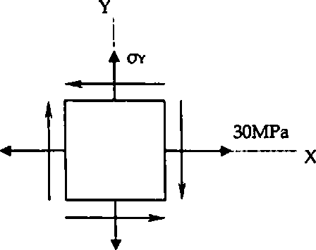
Q.5a The Figure 4 shows the state of stress at a point. Knowing that the maximum in-plane shear stress at this point is 10 MPa, determine the value of ay. Subsequently also find the values of principal
stresses and the corresponding principal planes and show them on properly oriented elements.
Q.Sb Derive an expression for the total deformation of a bar of tapering circular cross section from diameter dx to d2. The bar, fixed at larger end, is subjected to an axial load of F and has length /.
(14,06)
Q.6 A timber beam, 150 mm wide and 200 mm deep is reinforced at top and bottom with 6 mm thick aluminium plates of width b. The maximum bending moment in the beam is 14 kN-m. If the working stress in bending are 10 MPa for wood and 80 MPa for aluminium, determine the smallest allowable value of b. Use Eal/Ewd = 5.
(20)
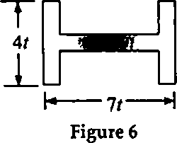
Q.7(a) Determine the equation of the elastic curve for the overhanging beam as shown in Figure 5; and calculate the value of deflection midway between the supports. The cross-section of the beam is shown in Figure 6. Take E 210 GPa.
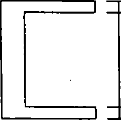
Q.7(b) A column pinned at both ends is made up from a section (thicknesses of web and flange are 20 mm) shown in Figure 6. The yield strength and modulus of elasticity are 248 MPa and 200 GPa respectively. Determine the allowable axial compressive load if the length of the column is 7 m.
|
900 N |
 |
|
Figure 3(a) |
 |
50 |
10 20
(AU Dimensions in mm)
Figure 3(b)
1.8 kN.m
 |
|
8MPa Figure 4 |
200N/m
k
LT
2m 2m 2m 2m Figure 5
|
Attachment: |
| Earning: Approval pending. |