Uttar Pradesh Technical University (UPTU) 2007-3rd Sem B.Tech Electrical Engineering , Network Analysis & Synthesis, 2006-07 - Question Paper
Open attachment to see the ques. paper.
Printed Pages : 7 TEE - 402
PAPER ID : 2052
(Following Paper ID and Roll No. to be filled in your Answer Book)
Roll No.
(SEM. Ill) EXAMINATION, 2006-07 NETWORK ANALYSIS & SYNTHESIS
Time : 3 Hours] [Total Marks : 100
Note : Answer all questions. All questions carry equal marks.
Attempt any three parts of the following :
6x3=20
O
(a)
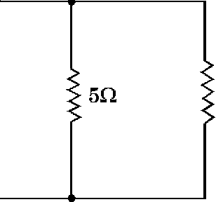
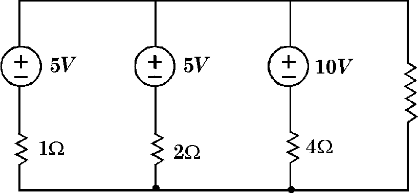
Using graph theory, find node voltages at X and Y for the network shown in Fig. 1 (a) 60 aaaaAAAAAA
 |
ion |
|
Fig. 1 (a) Write down the fundamental loop matrix of the network shown in Fig. 1 (b). |
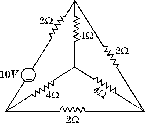 |
Fig. 1 (b)
(b)
|
1(U |  |
In graph theory, determine the relation between branch voltage matrix [V ], Twing voltage matrix [VT] and node voltage matrix [V ]. Draw the oriented graph of a network with fundamental outset matrix as shown below:
(C)
(d)
|
Twings Links | ||||||||||||||||||||||||||||||||||||
|
1 | |||||||||||||||||||||||||||||||||||
Also find no. of fundamental outsets and draw them.
Using graph theory prove that two given networks in Fig. 1 (e) (i) and 1 (e) (ii) and are duals to each other.
(e)
 |
|
Fig. 1 (e) (i) Fig. 1 (e) (ii) Attempt any three parts of the following : 62/3x3=20 (a) Find Voltage v ' using superposition theorem of the network shown in fig. 2 (a). |
3Q
-A/WV-
20.
-WA-
in
-A/sAA-
4>
3A
5Q
Fig. 2 (a)
2
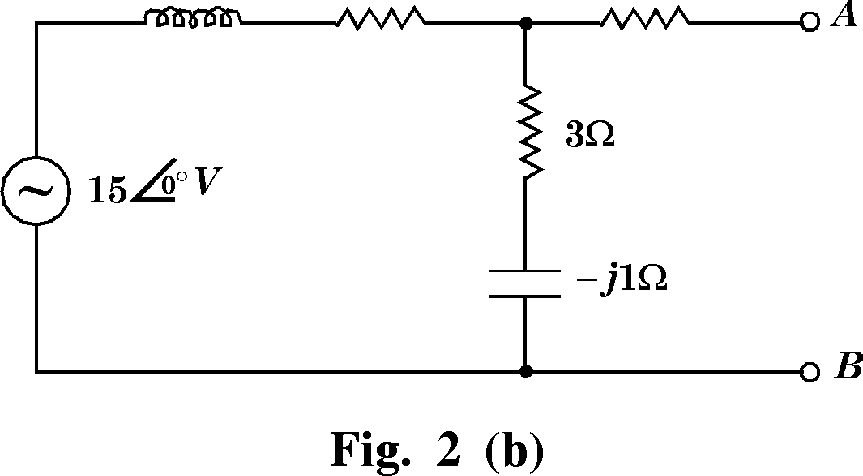
(b) Find the Nortons equivalent for the network given in fig. 2(b) across A and B.
2Q 4Q
(c) Determine the value of ZL for which it receives maximum power and calculate this power of the network shown in fig. 2 (c).
JvVA-
1Q
: 4Q
ZL
Fig. 2 (c)
(d) State Millmans theorem for voltage and current sources. Also find the current through RL in the network shown in fig. 2 (d) using millmans theorem.
 |
|
Fig. 2 (d) 3 |
(e) State compensation theorem. Find the change in current flowing through the impedance Z, when its value is changed from (4-j3) Q to (6+j8) Q using it in the network shown in fig. 2 (e).

Attempt any two parts of the following : 10x2=20
(a) Enlist the restrictions on location of poles and zeros in driving point function.
In the network of fig. 3 (a), find .
Also find the pole zero locations and draw pole-zero plate of it.
+
4 S
v(~)
(b) Obtain V2(s)/V1(s) of the network shown in fig. 3 (b) if
IQ Iff -AAMA__rtftytfin-
O-
+
-o
I
I
Fig. 3 (b)
(c) How can stability of the network be obtained with the help of pole-zero plot. Determine driving point impedance function of the network shown in fig. 3(c). Draw pole-zero plot and discuss stability of the network.
1H 1H 1H o-nsmnsff'--ns?svT5ff\--nssinnn
IF
IF
IF
A
A
A\
Z(S)
|
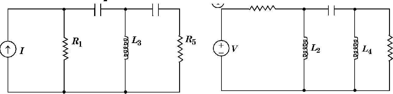
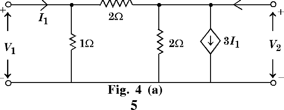
Fig. 3(c) Attempt any two parts of the following : 10x2=20 (a) Obtain Z-parameters of the network shown in fig. 4 (a). Whether the network is reciprocal and/or symmetrical. /2 |
 |
|
(b) Determine the h-parameters of the network shown in fig. 4 (b). 2 f |
 |
|
Fig. 4 (b) |
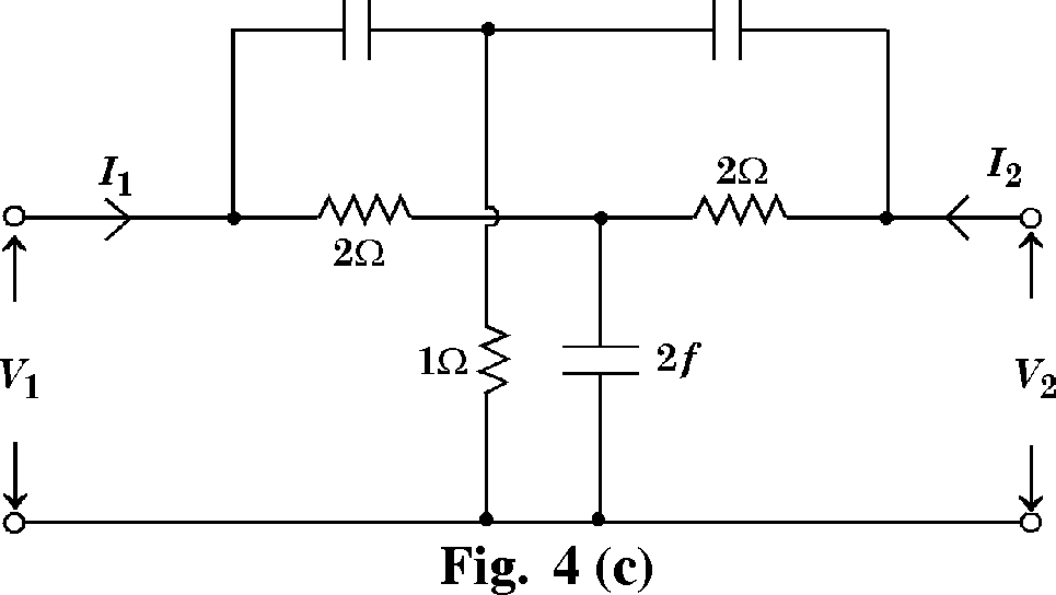
(c) Determine Y-parameters of two port network shown in fig. 4(c) using interconnection principle.
|
if if |
 |
5 Attempt any three parts of the following : 6 x3=20
O
(a) Design the T and n section of a prototype high pass filter having cut-off frequency of 20 kHZ and design impedance of 450 ohms. Also find its characteristic impedance and phase constant at 25 kHZ as well as determine the attenuation at 4 kHZ.
V-2052] 6 [Contd..
(b) In a series resonance type band pass filter, L = 60 MH, C = 150 nf and R = 70 ohms. Determine (i) resonance frequency in HZ,
(ii) Bandwidth (iii) cut-off frequencies. Assume the load resistance to be 600 ohms.
(c) Explain the advantages of active filters in comparison to passive filters.
An admittance function is given as
4s2 + 6s
s + 1
Realise the network using Cavers first and second form.
(d) Enlist the properties of driving point immittance of LC network.
State whether the following functions are driving point immittances of LC network or not:
10(s2 + 4)(s2 + 6)
(i) Z(s) = +-rP-r-f-
y> (s2 + l)(s2+s)
5s (s2 + 4j
(s2 +1) (s2 + 3)
8(s2_4)(s2 +25) s(s2 +16)
(iii) z(s)
(e) An impedance function at the input of a network is represented by
(s2 +5s + 4)
(s2 +2s)
Express it in the second faster form.
V-2052] 7 [ 4035 ]
|
Attachment: |
| Earning: Approval pending. |