Uttar Pradesh Technical University (UPTU) 2007 B.E Civil Engineering structural analysis - Question Paper
structural analysis
TEN - 402
*V-0069*
Printed Pages : 4
(Following Paper ID and Roll No. to be filled in your Answer Book)
PAPER ID : 0069
Roll No.
(SEM. IV) EXAMINATION, 2006-07 STRUCTURAL ANALYSIS
Time : 3 Hours] [Total Marks : 100
Note : (i) Attempt all questions.
(ii) All questions carry equal marks.
(iii) The symbols used have their usual meanings.
(iv) Assume any data not given.
1 Attempt any two questions of the following : 10x2=20
(a) Calculate the elastic section modulus for a rectangular beam of width b and depth d and a circular beam of diameter D.
(b) A rectangular beam 200 mm wide and 600 mm deep in simply supported over a span of 10 m and carries a uniformly distributed load of 24 kN/m. Calculate (Assume E=2xl05 N/mm2)
(i) Maximum stress at extreme fibres.
(ii) Radius of curvature at the section of maximum bending moment, and the stress at a distance of 100 mm below the top surface of the beam at that section.
(c) Show that for a rectangular beam of width b and depth d, the shear stress distribution over its cross-section is given by the formula
V (d2 S)
Also sketch the shear stress distribution over its cross section, and prove that the maximum shear stress in 1.5 times, the average shear stress. Also show the location of maximum and minimum shear stress in the sketch
2 Attempt any two of the following :
10x2=20
(a) A cantilever beam of length L is loaded with a uniformly distributed load w all along the span. Using the differential equation for slope and deflection of beam, derive the formula for slope and deflection at the free end of cantilever beam.
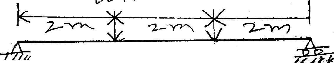
(b) A simply supported beam of span 6 m carries two concentrated loads of 60 kN and 15 kN as shown below in fig. 1. Find the deflection under 60 kN load and the position and magnitude of maximum deflection.
Assume E = 2 x 10⁵ MPa, I = 4 x 107 mm4
 |
|
Fig. 1 |
A simply supported beam of span L carries a concentrated load w at mid point. Using moment area method, determine slope at the ends and deflection at the mid point of the beam.
3 Attempt any two of the following : 10x2=20
(a) A thin cylinder of length 1.5m and internal volume 1.5 m3 is subjectd to an internal fluid pressure of 2.5 MPa. If the maximum permissible tensile stress is 170 MPa, determine the thickness of cylinder and the changes in volume. Assume E = 2 x 10⁵ MPa and Poission's ratio = 0.25.
(b) A thin spherical shell of 2m diameter is 15 mm thick. It is filled with liquid at internal pressure of 5 MPa. Determine hoop stress and change in volume of shell. Assume E = 2 x 10⁵ MPa and Poission's ratio = 0.3.
(c) A solid shaft of 200 mm diameter is to be replaced by a hollow shaft of external diameter 280 mm. Determine the internal diameter of the hollow shaft if the same power in transmitted at the same speed and at the same maximum shear stress by both the shafts. Also calculate the percentage saving in material by using the hollow shaft in place of solid shaft.
4 Attempt any two of the following : 10x2=20
(a) Derive the expressions, from first principles, for strain energy stored in structural members under direct load and bending.
(b) A simply supported beam of span L carries a concentrated load P at mid point. Considering strain energy due to bending only, determine the deflection of the beam at mid point. El is constant.
(c) A cantilever beam of span L carries a uniformly distributed load W over full span.
Using Castiglianols theorem, determine the vertical deflection and rotation of the free end. Assume El as constant.
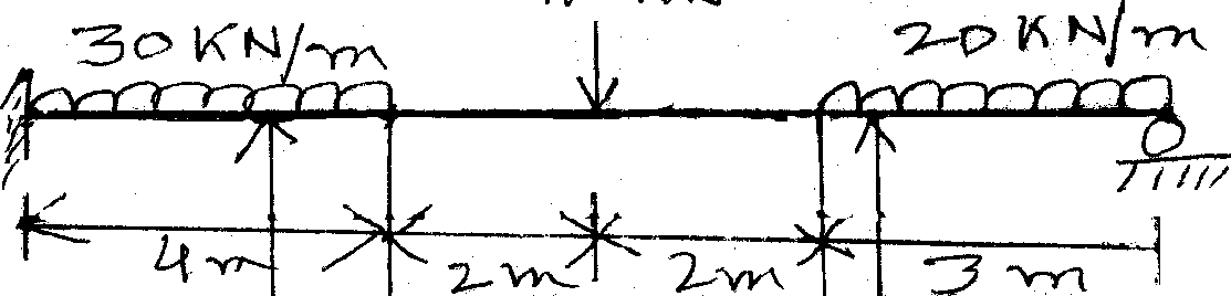
(a) Analyse the continuous beam as shown in fig. 2 and calculate the support moments and all reactions at supports. Use slope deflection method. E is constant, and the relative moments of inertia as shown in Fig 2. Draw the bending moment diagram.
 |
|
"7 * S 'T/y Fig. 2 |
*
I*
(b) Analyse the frame shown in fig. 3 using the moment distribution method, and draw the bending moment diagram. El is constant throughout.
 |
|
SY-i'A |

V _
77777
Fig. 3
V-0069] 4 [ 100]
|
Attachment: |
| Earning: Approval pending. |