Bengal Engineering and Science University 2006 B.E Civil Engineering Strength of Material-I - Question Paper
Friday, 18 January 2013 06:15Web
Page 1 of 2
ques. paper is in pdf format with attachment.
Ex/ BESUS/ AM-401/06 B.E. (CE) Part-II 4th Semester Examination, 2006
Strength of Materials I (AM-401)
Time : 3 hours Full Marks : 100
Use separate answerscriot for each half. Answer SIX questions, taking THREE from each half. The questions are of equal value.
Two marks are reserved for neatness in each half. Assume suitable data wherever missing.
FIRST HALF
1. An aluminium rod is rigidly attached between a steel rod and a bronze rod as
shown in Fig.Q.l. The cross-sectional areas of steel, aluminium and bronze rods
2 2 2 are 500 mm , 400 mm and 200 mm respectively. Length of each position is
shown in the figure. The compound bar is subjected to axial forces as shown. Final the maximum value of P, that will not exceed a stress in steel of 140 MPa, in aluminium of 90 MPa or in bronze of 100 MPa, and also the total change of length of the compound bar will not exceed 3.65 mm.
Assume Esteel = 200 GPa, Ea|uminium = 70 GPa and Ebronze = 83 GPa.
Steel
|
A 500 mm A - 400 mm |
|
4 P<- |
|
|
|
|
|
|
-af-2.5 m-jf-2.0 m-1.5 m-
[Fig.Q.lJ |
a) Define modulus of elasticity (E), modulus of rigidity (G) and Poisson's ratio (|a) of an elastic material.
b) Derive a relationship between E and G.
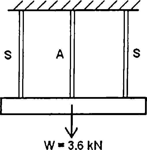
3. A rigid bar weighing 3.6 kN hangs from ceilling with three equally spaced wires, two of steel (marked as S) and one of aluminium (marked as A) as shown in figure Q.3. The diameter of the wires are 3 mm. Before they were loaded all the three wires had the same length.
What temperature increase AT in all the three wires would results in the entire load being carried by the steel wires only?
Assume : Es = 2 x 10⁵N/mm2, as = 12 x 10-6/C and aa = 23 x 10-6/C.
 |
|
|Fig.Q.3| |
4. a) A thinwalled (thickness t) closed conical vessel of height h and appex angle
2a, is filled with a gas at a pressure p. Find the expression for the principal membrance stresses at a point on the wall, at a depth Y below the apex.
b) The maximum instantaneous elongation produced by an unknown falling
weight W through a height of 40 mm in a vertical bar of length 5 m and of
2
cross-sectional area 500 mm is 1.8 m. Find the unknown weight W, assuming the modulus of Elasticity equals to 200 GPa.
5. a) Write down (without proof) the expression of shearing stress (x) induced in
the surface of a circular shaft of radius (r), when it is subjected to a twist (<{>) over a length (L) and a twisting moment (T).
b) State the assumptions to be made for deriving the above relationship.
c) In a hollow circular shaft of outer diameter and inner diameters 200 mm and 100 mm respectively, the maximum allowable shearing stress is 40 N/mm . Find the maximum power which the shaft can safely transmit when rotating at a speed of 300 rpm. What should be the angle of twist per unit length of the shaft? Assume G = 100 GN/m2.
SECOND HALF
6. A beam ABCD 7 m long is simply supported at A and C on a span of 5 m, CD being an overhang of 2 m. A uniformly distributed load of 4 kN/m acts on the simply supported span AC with a downward concentrated load of 11 kN acting at B at a distance of 2 m from the left hand end A. Another downward point load of 4 kN acts at the free end D. Draw the shear force and bending moment diagrams for the beam mentioning values at significant points. Find also the point of contra flexure, if any.
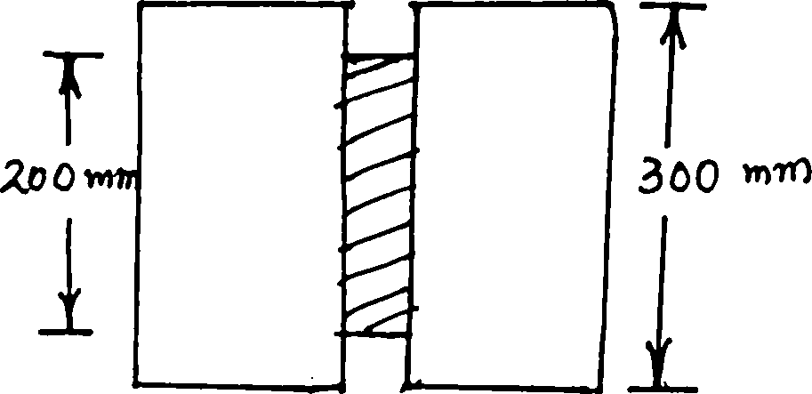
b) A flitched timber beam consists of two rectangular joists 100 mm wide and 300 mm deep with a steel plate 200 mm deep and 15 mm thick placed symmetrically between and clamped to them. Calculate the total moment of resistance of the section if the allowable stress in rectangular joists is 9 MN/m2. Given Es = 20 Ew. (Refer Fig.Q.7)
|<~ 100 f<r*IOO mn-fl
H W-mw
IFig.Q.7]
8. A beam of channel section 120 mm overall depth and 60 mm wide has uniform thickness of 15 mm for both flange and web. A vertical shear force of 50 kN is applied at one section. Draw the shear stress distribution diagram across the section mentioning important values. Also find the ratio between the maximum and the mean shear stresses.
9. a) Explain with neat sketches how in a beam subjected to transverse loading, horizontal shear stress is developed along with the vertical component.
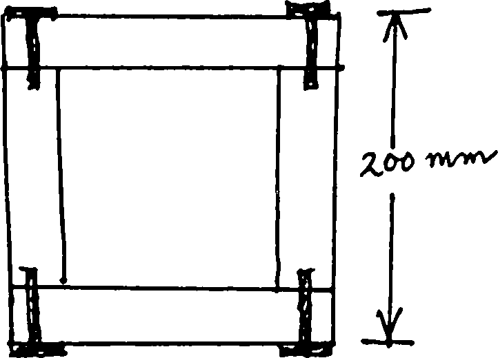
b) A box beam shown in Fig.Q.9 is made up of four 150 mm x 25 mm wooden planks connected by screws. Each screw can safely transmit a shear force of 1250 N. Estimate the necessary minimum spacing of screws along the length of the beam if the maximum shear force transmitted by the cross section is 5000 N. Sketch corresponding shear stress distribution across the section.
(AM-401)
10. A cast iron beam has a I-section with unequal flanges. The top flange is 80 mm wide and 20 mm thick, the bottom flange is 160 mm wide and 40 mm thick with the web 200 mm deep and 20 mm thick, the overall depth of the cross-section being 260 mm. The beam is freely supported over a span of 5 metres. If the tensile stress is not to exceed 20 N/mm , find the safe uniformly distributed load which the beam can safely carry. Find also the maximum compressive stress that is developed.
Add comment
| Earning: Approval pending. |
|
|