Bengal Engineering and Science University 2007 B.E Civil Engineering Strength of Material-II - Question Paper
ques. paper is with the attachment in pdf format.
Ex/ BESUS/ AM-501/07 B.E. (CE) Part-Ill 5th Semester Examination, 2007
Strength of Materials-II (AM-501)
Time : 3 hours Full Marks : 100
Use separate answerscript for each half.
Answer SIX questions, taking THREE from each half.
The questions are of equal value.
Two marks are reserved for neatness in each half.
FIRST HALF
1. A circular ring of mean radius R = 100 mm, breadth b=50mm and thickness t= 12 mm is subjected to a diametral pull along the vertical diameter at two diametrical opposite points. Find the maximum bending moment and the location where it occurs.
Find a general expression first and then insert numerical values.
2. a) Starting from the fundamentals, find an expression for critical load for a
long column having one end fixed and the other end hinged.
b) An ISMB 250 Rolled Steel Joist is to be used as a column 4 metres long with one end fixed and the other end hinged. Find the safe axial load on the column allowing a factor of safety of 3. Use Rankines formula.
Given, A = 4755 mm2, Ix = 5.1316 x 101 mm2, Iy = 3.345 x 103 mm4, oc = 320 N/mm4,
3. A channel section is of 400 mm overall depth 100 mm width of flanger measured from the back of the channel, 14 mm flange thickness and 8 mm web thickness. The channel is used as a cantilever 2 m long and a load P acts at the free end inclined 30 to the right of the vertical and passing through the shear centre. Determine the value of the load P if allowable stresses for tension and compression are 150 N/mm2 and 100N/mm2 respectively. Given, x (from channels back) = 26.3 mm, Ix = 1.38662 x 105 mm4, Iy = 5.401872 x 106 mm4.
5. a) Starting from the fundamentals, derive an expression to compute the bending stress for a curved beam, subjected to a bending moment tending to reduce the curvature. Draw a neat sketch and explain the symbols clearly.
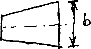
b) A semi-circular curved bar is loaded as shown in Fig.Q.5(b). The bar has a trapezoidal section with a = b = h = 2cm and P = 500N, the symbols having their usual significance. Calculate the maximum tensile stress and indicate where it occurs. Draw the stress distribution diagram across the section.

 |
|
f |
Fig.Q.5(b)
SECOND HALF
6. At a point in a vertical cross-section of a beam there is a resultant stress of 50 MPa,
which is inclined upward at 35 to the positive direction (towards right) of the
horizontal axis. On the horizontal plane through the point there is only shearing stress. Find the resultant stress on the plane which is inclined at 40 to the vertical
and 95 to the given resultant stress, both in magnitude and direction with respect
to the horizontal plane.
7. The following strains, expressed in micro meter per meter have been measured by a 45 strain rosette : a = 232 at 0, = 123 at 45 and ec = -80 at 90. Determine the principle strains and principal axes. If E = 210 GPa and n = 0.3, determine the principal stresses.
9. A simply supported prismatic beam of length 7 carries a concentrated load P at a distance b from the right support. Locate the point of maximum deflection on the elastic line and find the value of this deflection. [11]
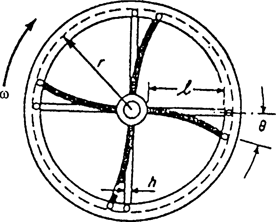
The rim of a fly wheel of weight W and mean center-line radius r is attached to a hub by four spokes as shown in Fig. 10(a). Each spoke has a rectangular cross-section of dimensions bxh and a length 7. The spokes are built in at the hub and pinned at the rim. While the wheel rotates with constant angular velocity co\ the hub is suddenly locked. What maximum bending stress will be induced in each spoke where it joins the hub? Neglect the weight of the spokes.
10. a)
 |
|
Fig.lO(a) |
b) A simply supported beam with overhang is loaded as shown in Fig.Q. 10(b). If a = 1/2, find the ratio P/W to make the deflection at D to zero. [5+61
W*wi
Fig. 10(b)
the natural frequency of the system in Hertz.
A simply supported weightless beam of 6000 mm length has a rectangular cross-
mid-point of the beam through a spring of spring constant 40 N/mm. Determine
section of 150 mm depth and 100 mm width. A weight of 20 N is suspended at the
A propeller of 60 kN weight is carried by a shaft of 0.22 m diameter and overhangs the supporting bracket by 0.44 m. The propeller receives 3000 kW at a speed of 300 r.p.m. If the propeller thrust is 150kN, calculate the principal stresses at the following points on the surface of the shaft at the support:
(a) when the point is at the bottom of the shaft, (b) when it is at the end of the horizontal diameter, (c) when it is at the top of the shaft.
|
Attachment: |
| Earning: Approval pending. |