Bengal Engineering and Science University 2007 B.E Civil Engineering Structural analysis - Question Paper
ques. paper is with the attachment.
Ex/BESUS/ CE-401/07 B.E. (CE) Part-II 4th Semester Examination, 2007
Time : 3 hours Full Marks : 70
Use separate answerscript for each half.
Answer SIX questions, taking THREE from each half.
The questions are of equal value.
Two marks are reserved for neatness in each half.
FIRST HALF
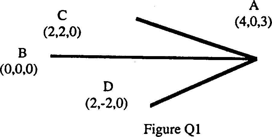
1. Figure Q1 shows the plan of a space truss. The ends B, C and D are simply supported in same horizontal plane. A load of lOOkN is acting vertically downward at A. Find the forces in all members. The co-ordinates of joints are shown in bracket.
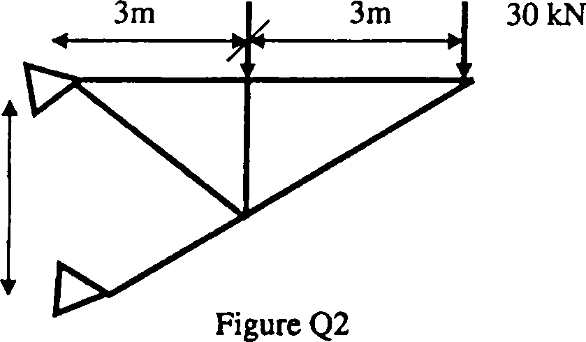
2. A plane truss is shown in figure Q2. Find the vertical deflection at joint where the load of 30kN is acting. Assume modulus of elasticity as 200GPa and cross section area as 300mm2 for all members.
|
20 kN |
 |
| ||||||||||
|
Figure.Q.7 | ||||||||||
8. Explain Muller-Breslans Principle in connection with influence line diagram.
r
I
-LtxwfoiL- vivivfey = EX
Draw the influence the diagrams for bending moment and shear force at point B of the simply supported beam as shown in Figure.Q.8.
A
>*-
Figure.Q.8
9. Explain what you understand by conjugate beam. Find out the deflection at the middle point of the simply supported beam as shown in Figure.Q.9.
.2 EX
El
+ i. n
| ||||||
|
Figure.Q.9 |
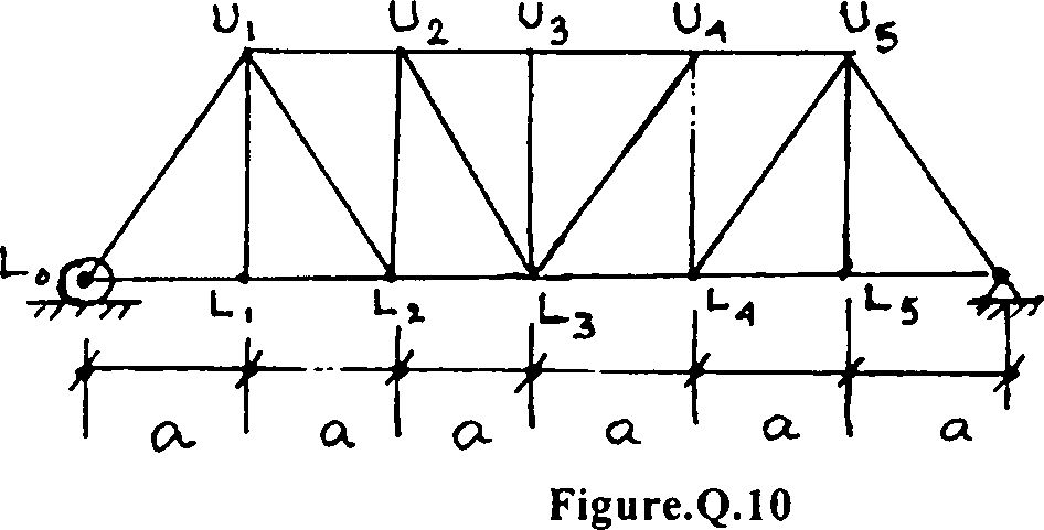
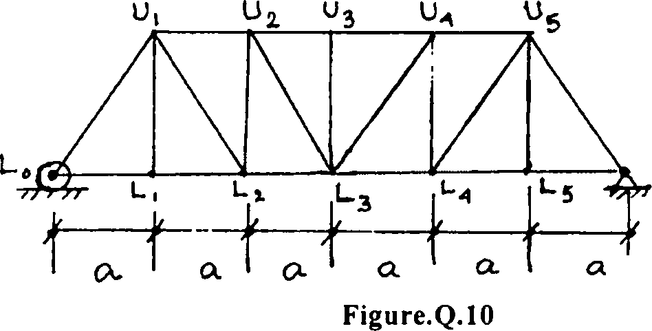
10. Draw the influence line diagram for the member U2L3 of the truss shown in Figure.Q. 10. Consider all the spans of the truss are equal. All members of the truss have cross sectional area A and modulus of elasticity E.
-
LixwroU fvvK-fcy = EX %n
r
I
&
| ||||||||||
|
Figure.Q.7 | ||||||||||
8. Explain Muller-Breslans Principle in connection with influence line diagram.
Draw the influence the diagrams for bending moment and shear force at point B of the simply supported beam as shown in Figure.Q.8.
Figure.Q.8
9. Explain what you understand by conjugate beam. Find out the deflection at the middle point of the simply supported beam as shown in Figure.Q.9.
.2EX
ex
|
y |
f 1 | |
|
/ " 7 1 e 1 4 |
r ) e 2. Figure.Q.9 |
e 1 1 |
10. Draw the influence line diagram for the member U2L3 of the truss shown in Figure.Q. 10. Consider all the spans of the truss are equal. All members of the truss have cross sectional area A and modulus of elasticity E.
-M-
|
Attachment: |
| Earning: Approval pending. |