Bengal Engineering and Science University 2007 B.E Civil Engineering Theory of structures-I - Question Paper
ques. paper is with the attachment.
Ex/BESUS/ CE-501/07 B.E. (CE) Part-Ill 5th Semester Examination, 2007
Theory of Structures-I (CE-501)
Time : 3 hours Full Marks : 100
Use separate answerscript for each half. Answer SIX questions, taking THREE from each half. Two marks are reserved for neatness in each half.
FIRST HALF
(The questions are of equal value.)
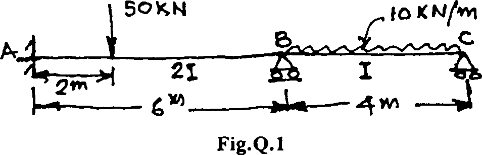
1. Analyse the beam loaded as shown in Fig.Q.l by moment distribution method. Also draw BM diagram.
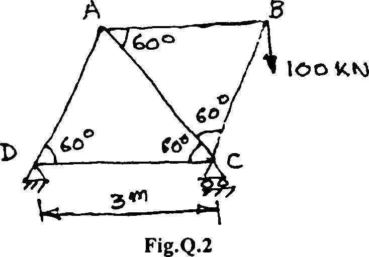
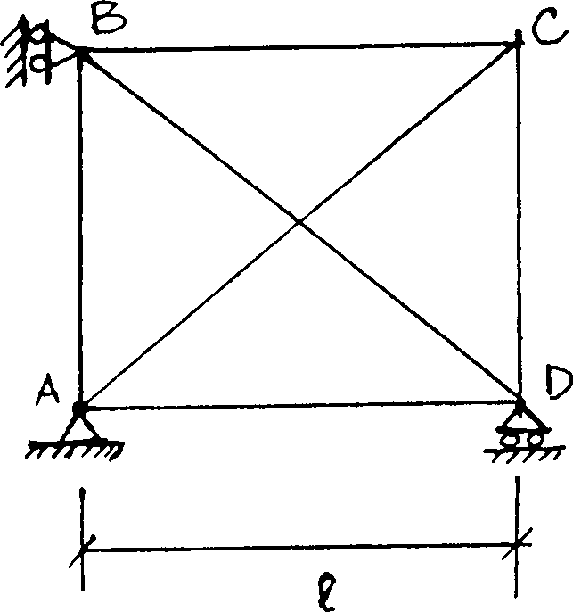
2. Find the horizontal deflection of mode B by virtual work method. AE = constant for all members shown in Fig.Q.2.
3. Calculate the redundant reaction at C and also draw BM diagram in Fig.Q.3.
A*
oi
I
u
-T7T
Fig.Q.3
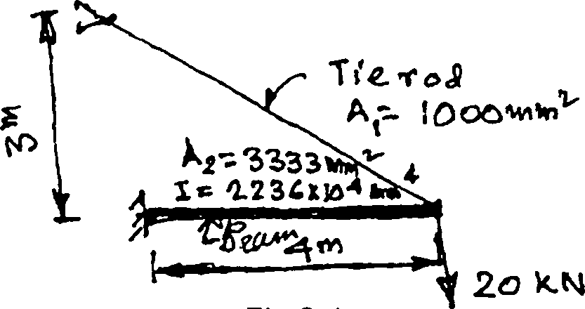
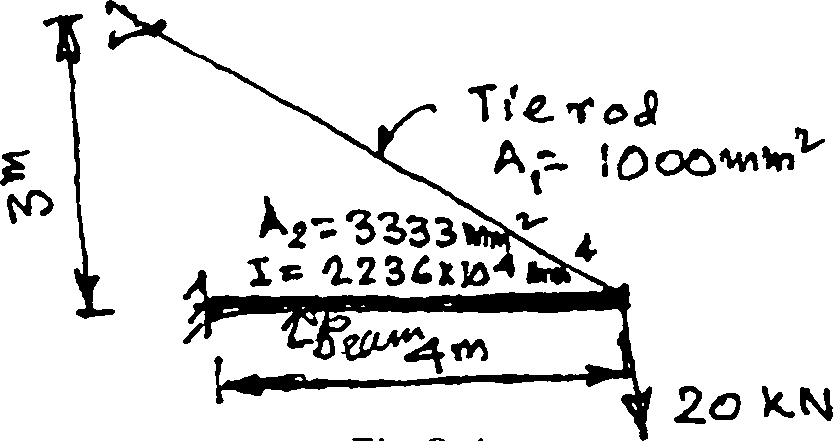
4. Calculate the tension in the tie rod as shown in Fig.Q.4.
 |
|
Fig.Q.4 |
5. Write short notes on any four of the following :
i) Castiglianos Theorems
ii) Strain energy and complementary strain energy
iii) Virtual work method for axial load
iv) Rotational and modified stiffness
v) Carry over and distribution factor.
SECOND HALF
State and explain two area-moment theorems.
Consider a beam AB which is supported on a hinge at the end A and supported on a roller at end B. It is having a span of 5.4m. A concentrated load of 120 kN is applied at a distance of 1.8 m from left hand support A. Find out by moment area method, the rotations of beam at its two ends, namely, 0A and 0B, respectively, and the deflection at the midspan. [5+11]
7. Referring Fig.Q.7, find by conjugate beam method, the rotations 0A and 0B at the two ends of the beam AB and the deflection at the midspan. [16[
2X
V1
E.I
a?
A t4T
.t-
Fig.Q.7
Derive the three moment equation including the effect of support settlement. Using this equation, draw the bending moment diagram of a four span continuous beam ABCDE which has all the spans AB = BC = CD = DE = 5 m and subjected to a uniformly distributed load of 10 kN/m. The beam is supported by a hinge at support A while it is supported on rollers at point B, C, D and E, respectively. [7+9]
4. Calculate the tension in the tie rod as shown in Fig.Q.4.
 |
|
Fig.Q.4 |
5. Write short notes on any four of the following :
i) Castiglianos Theorems
ii) Strain energy and complementary strain energy
iii) Virtual work method for axial load
iv) Rotational and modified stiffness
v) Carry over and distribution factor.
SECOND HALF State and explain two area-moment theorems.
Consider a beam AB which is supported on a hinge at the end A and supported on a roller at end B. It is having a span of 5.4m. A concentrated load of 120 kN is applied at a distance of 1.8 m from left hand support A. Find out by moment area method, the rotations of beam at its two ends, namely, 0A and 0B, respectively, and the deflection at the midspan. [5+11]
7. Referring Fig.Q.7, find by conjugate beam method, the rotations 0A and 0B at the two ends of the beam AB and the deflection at the midspan. 116]
2X
l/l
El
a?
EX
A
Ar
.6-
m
Fig.Q.7
Derive the three moment equation including the effect of support settlement. Using this equation, draw the bending moment diagram of a four span continuous beam ABCDE which has all the spans AB = BC = CD = DE = 5 m and subjected to a uniformly distributed load of 10 kN/m. The beam is supported by a hinge at support A while it is supported on rollers at point B, C, D and E, respectively. [7+9]
- (3) -
9. Explain what you understand by Influence line diagram of any structural member. Explain Muller Breslau principle in this context.
Consider the beam ABC which has span AB simply supported at A and B and has an overhang BC. Span AB is 8 m long and span BC is 2 m long. Calculate the maximum positive and negative reactions RA due to three concentrated loads as shown in Fig.Q.9. [2+3+111
30 Km
A
|
37 | ||||||||
| ||||||||
|
Fig.Q.9 | ||||||||
10. Explain the concept of analysing a truss by tension coefficient method.
Using tension coefficient method, determine the forces in the members of the truss shown in Fig.Q. 10. The axial rigidity is 2AE for horizontal and vertical members and AE for diagonal members. 15+11]
 |
|
Fig.Q.10 |
HO KN 151<N 0
JiD
B
C
2m 3wv |
|
Attachment: |
| Earning: Approval pending. |