Bengal Engineering and Science University 2007 B.E Civil Engineering Theory of structures-II - Question Paper
ques. paper is with the attachment.
B.E. (Civil) 6,h Semester Examination, 2007
Theory of Structures II (CE - 601)
Full Marks - 100 Time - 3 hrs
Answer any six questions, taking three from each half.
Two marks are ret'irved in each half for neatness and to the point answer.
FIRST HALF
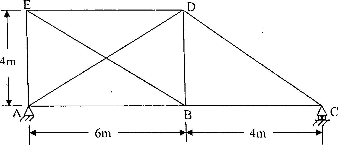
Q.l) In the plane braced frame shown in Fig. Q.l the members have the same cross-sectional area of 10 cm2 and are made of the same material. The member AD in the frame was initially short by 0.25 cm. Determine the force in each member.
Given : E = 2 x 10s N/mm2.
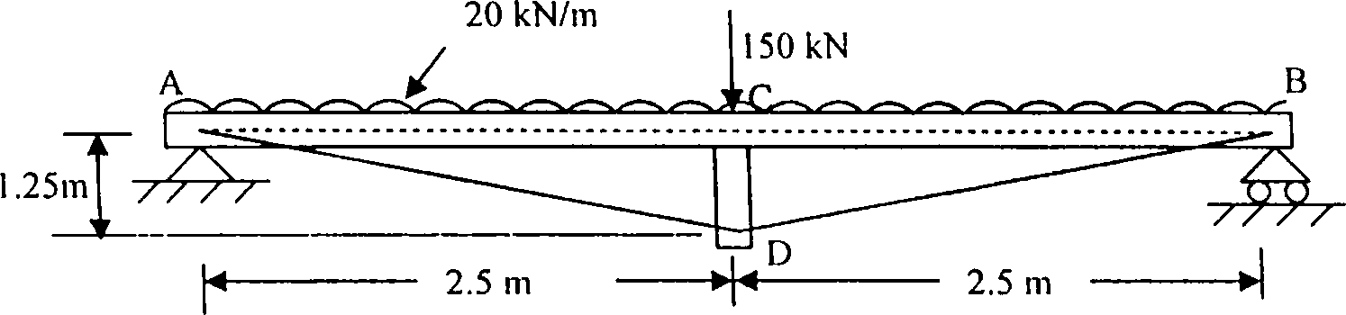
Q. 2) Fig. Q.2 shows a trussed beam that consists of the following:
(i) a timber beam AB, 150mm wide, 200mm deep, simply supported over a span of 5m.
(ii) a timber strut CD, 1.25m long with a cross sectional area of 800mm2.
(iii) two steel tie rods AD and BD, each with a cross sectional area of 600 mm2 connecting the bottom of the strut and the ends of the beam.
The beam carries a uniformly distributed load of 20 kN/m and a single concentrated load of 150 kN at the midspan. Find the force in the strut and the tie.
Given: E for steel = 2x10 N/mm2; E for timber = 1 x 10⁴ N/mm2.
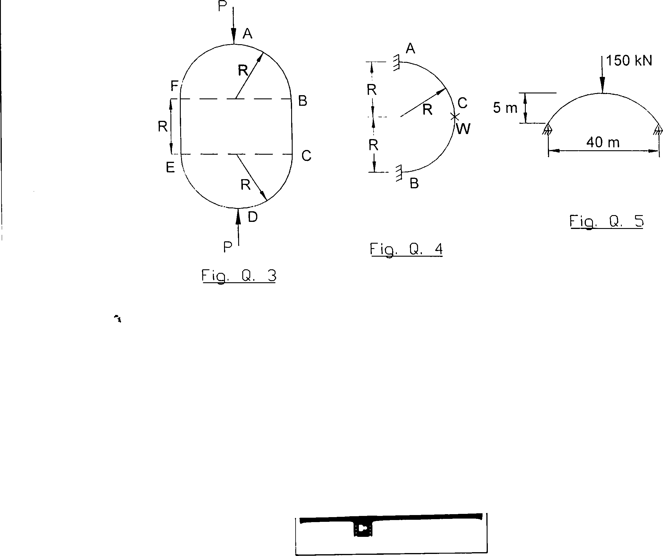
Q. 3) The link shown in Fig. Q. 3 consists of two semi-circles and two straight portions of constant section throughout. It is subjected to the action of two equal and opposite axial forces P! acting along the vertical axis of symmetry. Assuming that the cross-sectional dimensions of the link are small in comparison to the radius R\ determine (i) the B.M. at A, B and at the midpoint of BC, (ii) the shortening of AD.
Q. 4) Determine the B.M. and twisting moment at A and C of the semicircular beam of radius R shown in Fig. Q. 4. It is loaded with a load W at the mid-point of the semicircle. Draw the B. M. diagram.
Q. 5) A two-hinged parabolic arch as shown in Fig. Q. 5 has a span of 40 m and a central rise of 5 m. It carries a single concentrated load of 150 kN at the crown. The moment of inertia at any section is equal to /Csec0, lc being the moment of inertia at the crown and 0 the slope at the section. Determine the horizontal thrust at the supports and the B.M. at the crown, neglecting the effect of rib shortening. Draw the B. M. diagram.
 |
|
Fig.Q. 1 |
 |
|
Fig. 0. 2 |
Q. 6) The cab'es of a suspension bridge have a span of 100m and a central dip of 10m. Each cable is stiffened with a three - hinged girder and carries a dead load of 10 kN/m. In addition, there is a live load of 30 kN/m and 50m long. Determine the horizontal thrust at the cable supports and the maximum tension in the cable when the live load is situated on the left hnd half of the stiffening girder with its right end over the central hinge. Draw the B. M. diagram for the girder and indicate the values of maximum sagging and hogging B.M.
Q. 7) Analyze the continuous beam loaded as shown in Fig. Q. 7 by either the Slope Deflection Method or the Moment Distribution Method. Calculate the joint moments and sketch the B. M. diagram.
kN/m
10
5 kN/m
20 kN
v v v v v v \t v v v \t v \f \( v v v v n< v v v v w v v v
/
21
U-2m-
1
4m
21
6m
->*-
Fig. 0-7
Q. 8) Analyze the frame shown in Fig. Q. 8 by either the Slope Deflection Method or the Moment Distribution Method. Find the amount of sway in the frame, calculate the moments at the joints and draw the B. M. diagram.
50 kN
3 m
El = constant
5 m
777
FigJI_8
777
|
Attachment: |
| Earning: Approval pending. |