Bengal Engineering and Science University 2007 B.E Civil Engineering Bridge Engineering - Question Paper
the ques. paper is with the attachment.
B.E. (Civil) Part-IV 8th Semester Examination, 2007 BRIDGE ENGINEERING (CE-804/1) (Elective-II)
Time : 3 hours Full Marks : 100
Answer six questions taking any three from each half All questions carry equal marks Two marks are reserved for neatness in each half Draw neat sketches where ever required Assume reasonable data if not mentioned Use of IRC codes are permitted
FIRST HALF
1. List the loads and stresses to be considered while designing a highway bridges. State briefly the category of live loads as specified in IRC code of practice.
State the conditions under which increased stresses may be permitted over the permissible working stresses.
2. Design a RC one-way slab bridge for a National highway to suit the following data. Carriageway - two lane 7.5m wide
Footpaths - 1.25m wide on either side
Clear span - 7.0m
Wearing coat - 80mm
Width of bearing - 350mm
Loading - IRC class AA tracked vehicle
Impact factor - 18 %
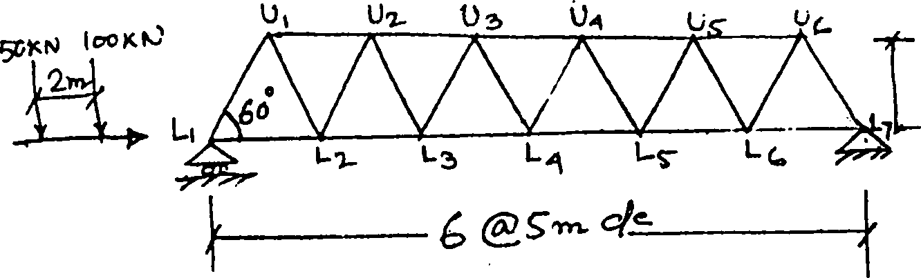
3. A warren girder having a span of 30m consists of six equal panels. Draw the influence lines for forces in the members L3L4, U3U4, and U3L4. Find also the maximum force in the member U3L4 due to train of loads shown in the figure Q3.
4. A composite bridge of effective span 18m with RC deck slab and steel plate girders is subjected to IRC class AA load for tracked vehicle. Data given are :
Clear width of roadway = 7.5m Footpath = 1.0m on either side Spacing of three main girders = 3.0m Spacing of five cross girders = 4.5m Design the shear connectors.
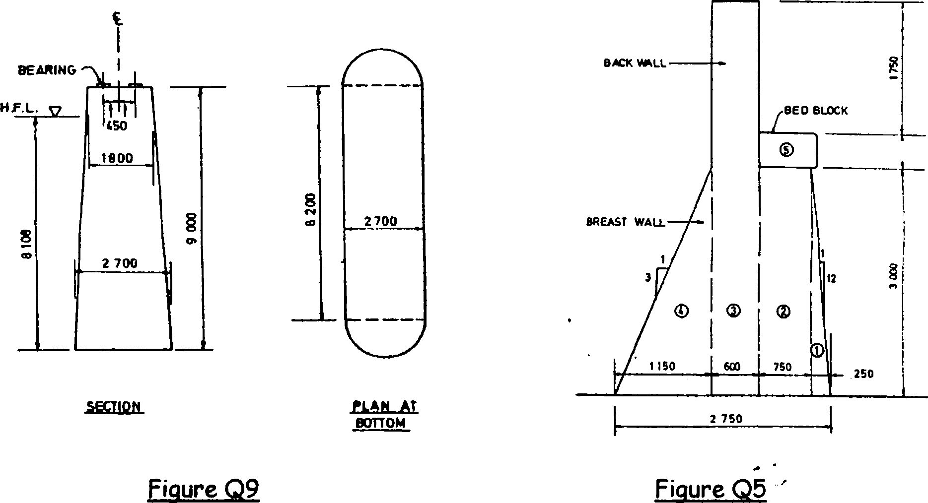
5. Draw a neat sketch of the mass concrete abutment for a highway bridge showing the dirt wall, wing wall and other components in plan and sectional elevation. List the loads and forces to be considered for design of an abutment.
A mass concrete abutment as shown in the figure Q5 is carrying a superstructure designed for IRC classAA tracked vehicle. Take dead and live load from superstructure as 950KN and 700KN acting on its width of 8.8m. Abutment back is filled with gravel of angle of repose 40 and unit weight of 18KN/m3. Angle of internal friction of back fill on abutment is 20. Adequate approach slab is provided. Calculate the stresses at base.
6. State the characteristic of an ideal bridge site across a river. What are the preliminary data to be collected during investigation for a bridge to be constructed across a river?
Calculate the linear waterway and mean scour depth if the design discharge is 1000 m3/sec and silt factor is 0.8. If the linear waterway is restricted to 100m with two intermediate pier foundations having average 2.75m obstruction to flow for each pier, what will be the mean scour depth? Also determine the minimum depth of foundation in each case.
! <
7. Calculate the foundation pressures at the base of the circular Well Foundation with the following data.
Depth of Well=25.0m
Diameter of well=8.0m
Depth below maximum scour=12.0m
Longitudinal force=1000KN acting at 37m above the base of the well under seismic
condition j
Weight from superstructure=8500KN
Weight of pier=1500KN
Weight of well=9000KN
Soil character: C=20KN/m2, ip=15 and unit weight (dry) =18KN/m3
8. Classify bridge bearings according to its function and material used.
What is Elastomeric bearing and what are its advantages.
Design a restrained elastomeric bearing under a precast prestressed girder for a bridge of 25m effective span. The width of the girder is 375mm. Data given:
Maximum reaction under a girder, Nmax=765KN
Minimum reaction under a girder, NLn=405KN
Breaking force at each end of a girder,H=15KN
Total rotation of the girder at the support,a bd=1.3xl0'3radian
Shear modulus of the bearing=0.83MPa
9. Determine the stresses at the base of the pier as shown in the figure Q9 with data given as follows.
Superstructure : simple slab-girder type with 21.3m span Foundation: well foundation
Pier dimensions : as shown in figure *
Dead load from each span=2250KN !
Live load from each span=900KN
Maximum mean velocity of water current=3.6m/sec i
Live load : IRC ClassAA or ClassA whichever produces severe effect
Only straight portion of the pier cross section to be considered for design. Neglect
seismic effect. -
10. Design the main girder of a RC T-beam girder bridge to suit the following data.
Clear width of the roadway=7.5m
Span at centre to centre of bearings=20m
Live load : IRC ClassAA tracked vehicle
Average thickness of wearing coat=100mm
Concrete and steel grade : M25 and Fe415
Spacing for three main girders=2.5m
Thickness of deck slab=200mm
Depth of main and cross girder=2000mm each
Width of main and cross girder=400mm each
Spacing of cross girders=4m
Kerb=600 wide x 300 deep
Impact factor= 10%
Figure Q3
 |
4S0 |
|
Attachment: |
| Earning: Approval pending. |