B.E-B.E 1st Sem Engineering Graphics-I (University of Pune, Pune-2013)
UNIVERSITY OF PUNE
[4361]-6
B. E. ( Semester-I) Examination-2013
Engineering Graphics-I
(2008 Pattern)
[Total No. of Questions : 12] [Total No. of Printed Pages :7]
[Time: 4 Hours] [Max. Marks: 100]
Instructions :
(1) Answer one question from each unit. Answer three questions from section-I and three sections from section-II.
(2) Answers to the two sections should be drawn on separate drawing-sheet.
(3) Use only half imperial size drawing papers as answer sheets.
(4) Assume suitable data if necessary and retain all construction lines
SECTION-I
UNIT-II: ENGINEERING CURVES
Q1. a) Draw an ellipse by rectangular method, if the major and minor axes are 100
mm and 60mm respectively. [8]
b) Draw an Archemedian spiral for one convolution, given that the radius is 60 mm. [7]
OR
Q2. a) Construct a hyperbola by focus-directrix method, if the distance of focus
from the directrix is 60 mm and eccentricity 3/2. [8]
b) Draw a cycloid of rolling circle of diameter 60 mm. [7]
UNIT-III: ORTHOGRAPHIC PROJECTIONS
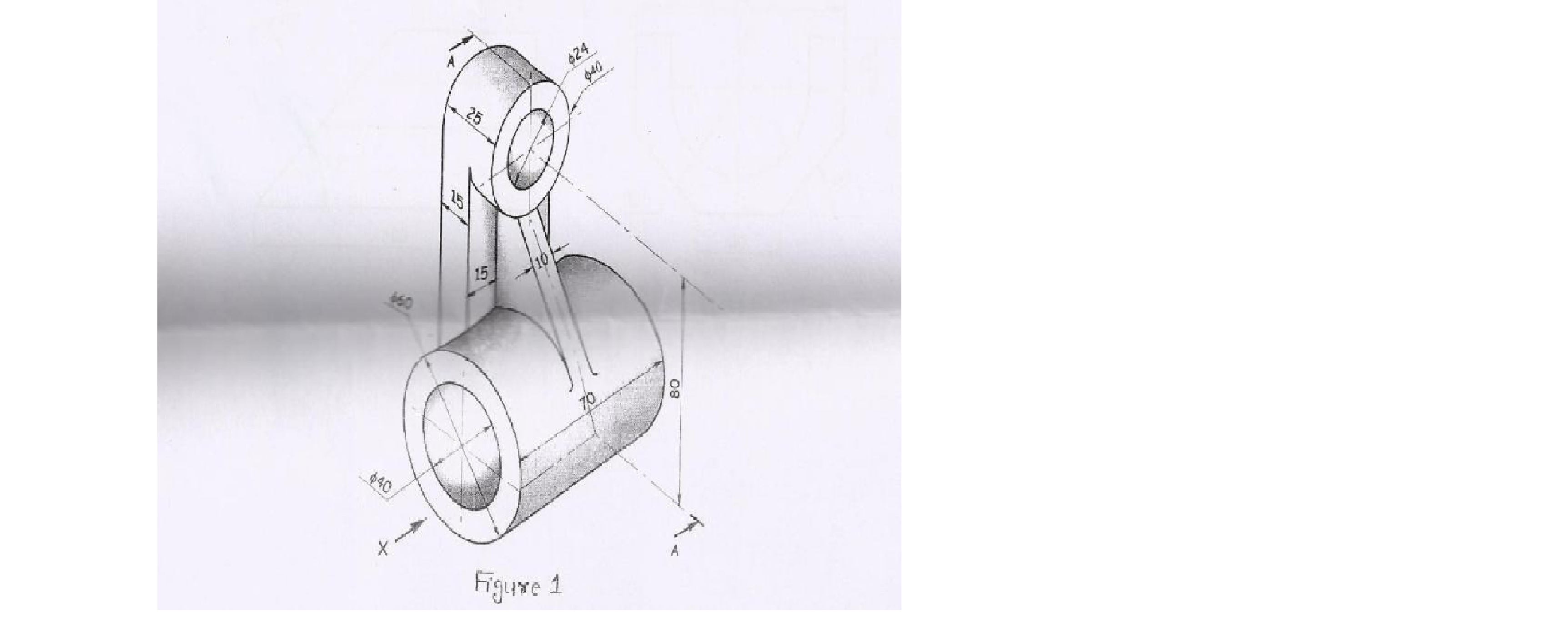
Q3. Figure 1 shows a pictorial view of an object. Draw sectional elevation along
section A-A, plan and right side view. Give the dimensions. [6+6+6+2] [20]
OR
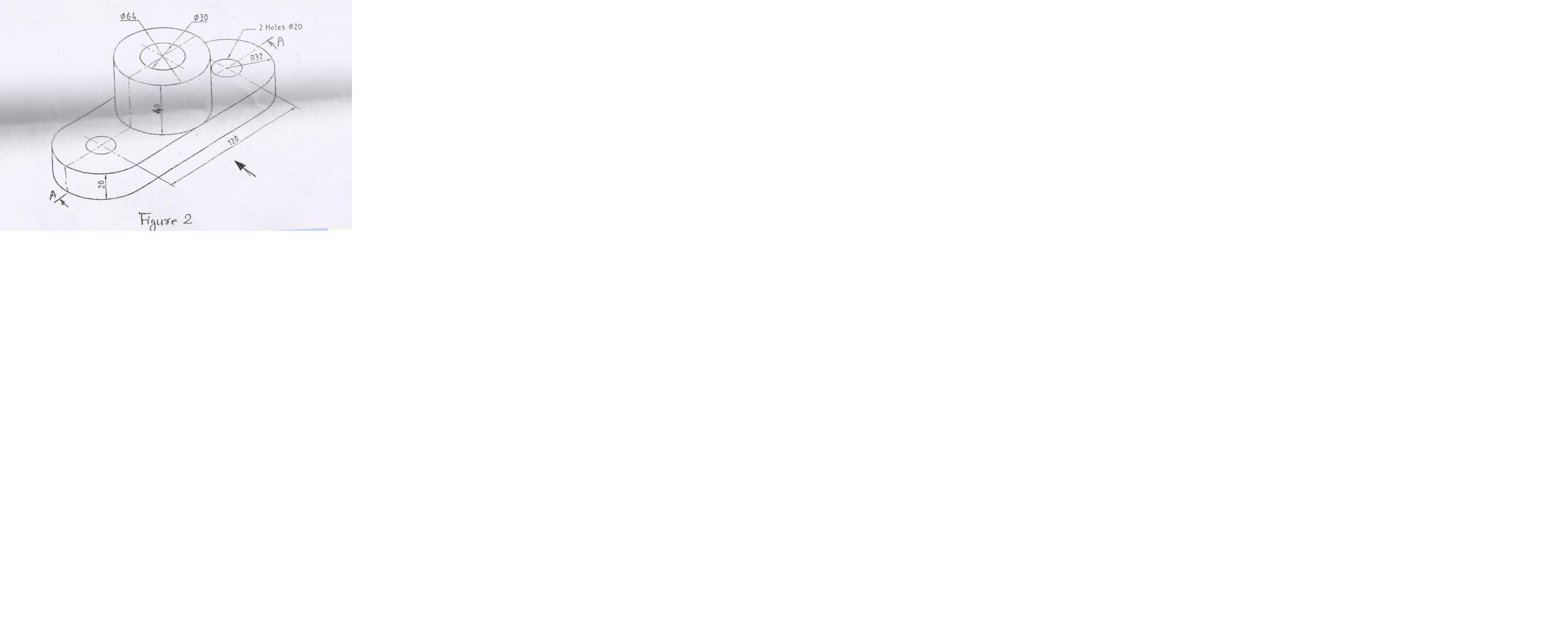
Q4. Figure 2 shows a pictorial view of a bracket. Draw sectional elevation along
sectional A-A, plan and left side view. Give the dimensions. [6+6+6+2] [20]
UNIT-IV: AUXILIARY PROJECTIONS
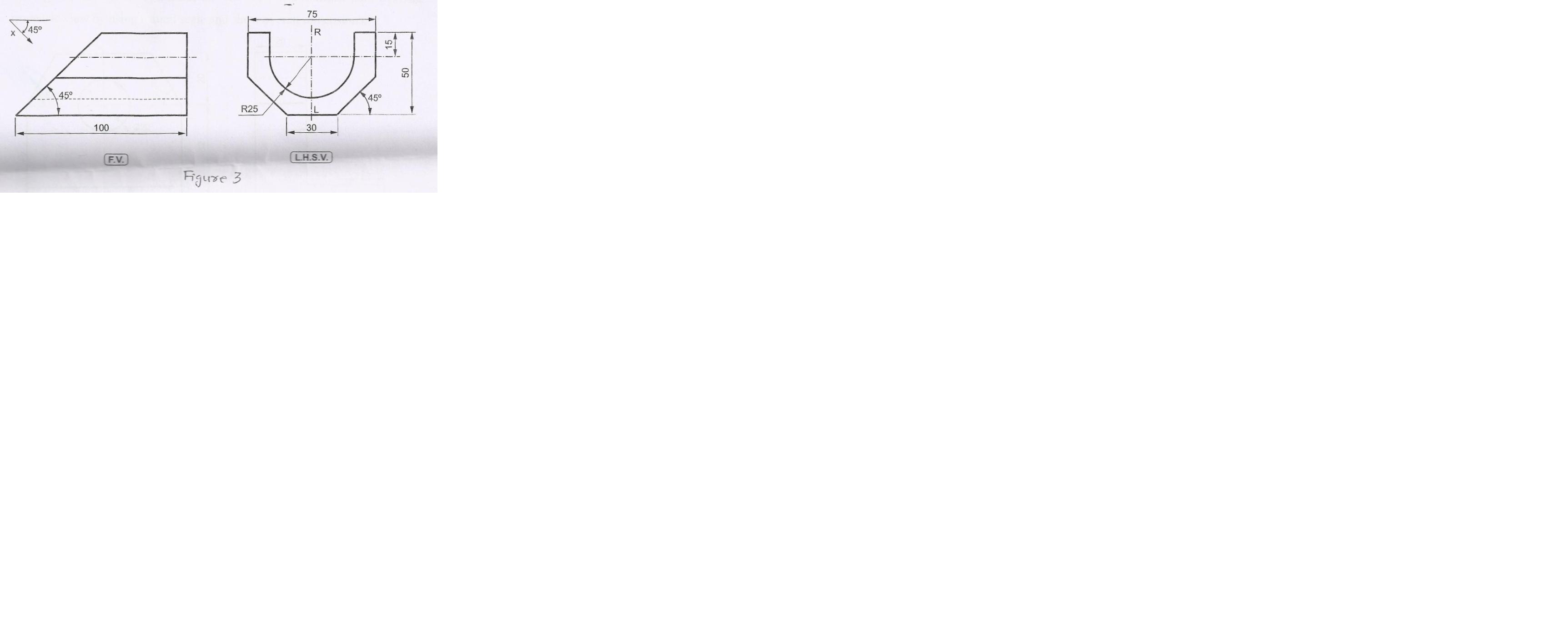
Q5. Figure 3 shows front view and left side view of an object. Redraw the given
view and draw an auxiliary view in the direction of X as shown in figure. Show the
dimensions. [5+8+2]. [15]
OR
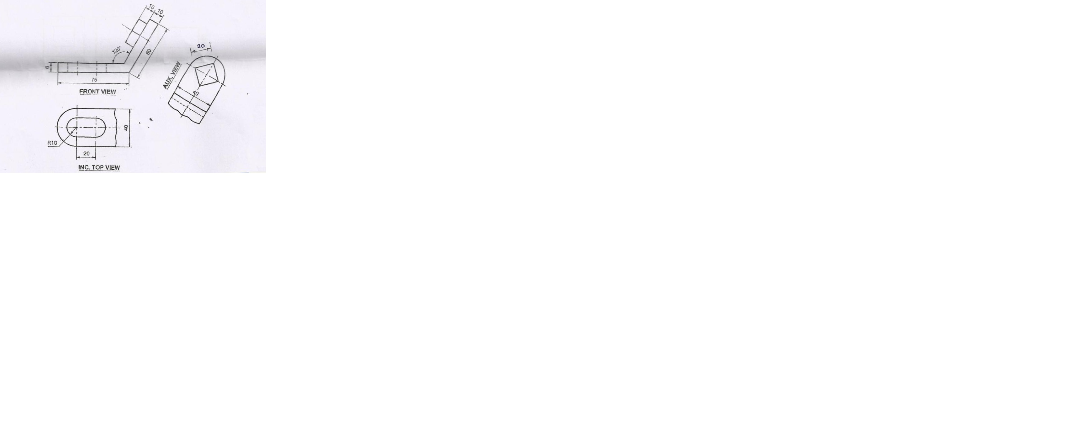
Q6. Figure 4 show front view, incomplete top view and incomplete auxiliary view
of an object. Redraw the given views and complete the top view. Show the
dimension. [5+8+2]. [15]
SECTION-II
UNIT-V: ISOMETRIC.
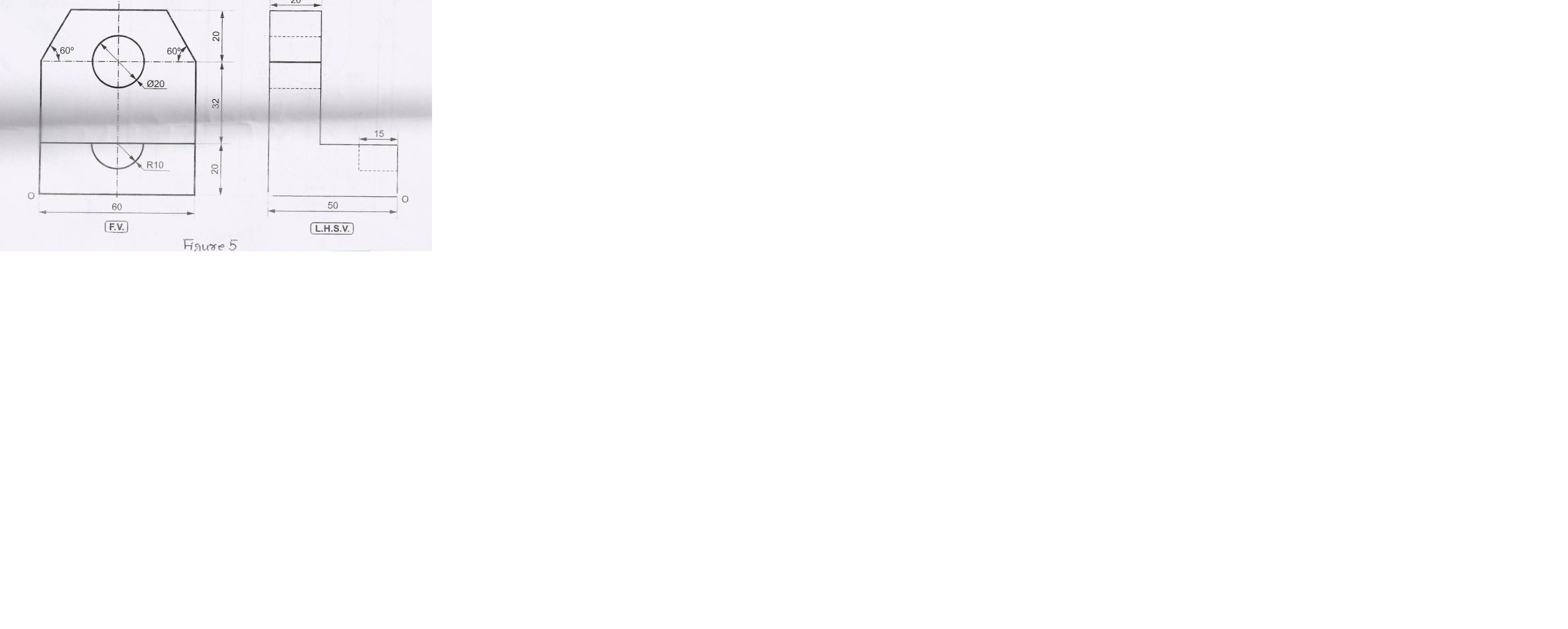
Q7. The figure 5 shows front view and left end view of a machine part. Draw its
isometric view by using natural scale and show overall dimensions. [20]
OR
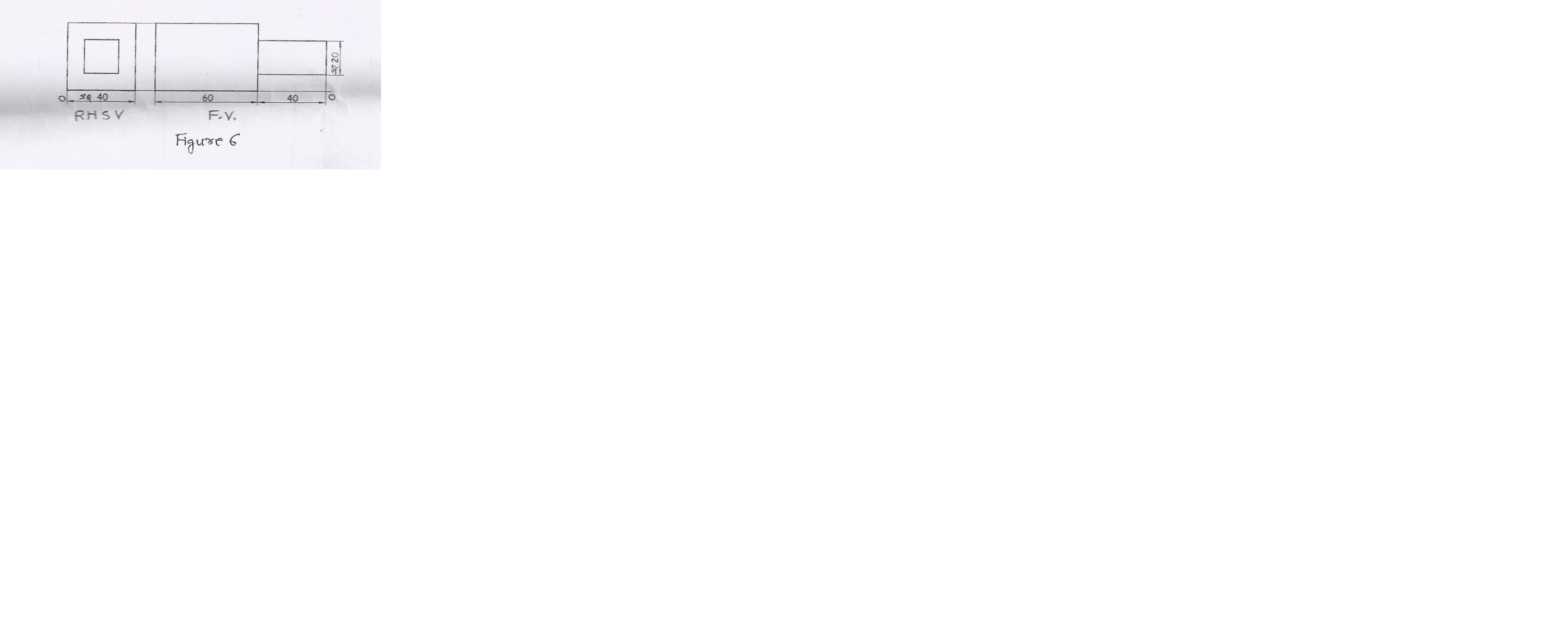
Q8. The figure 6 shows front view and right hand side view of machine part. Draw
its isometric projections by using isometric scale. [20]
UNIT-VI: MISSING VIEWS
Q9. The figure 7 shows front view and side view of a machine part. Draw [20]
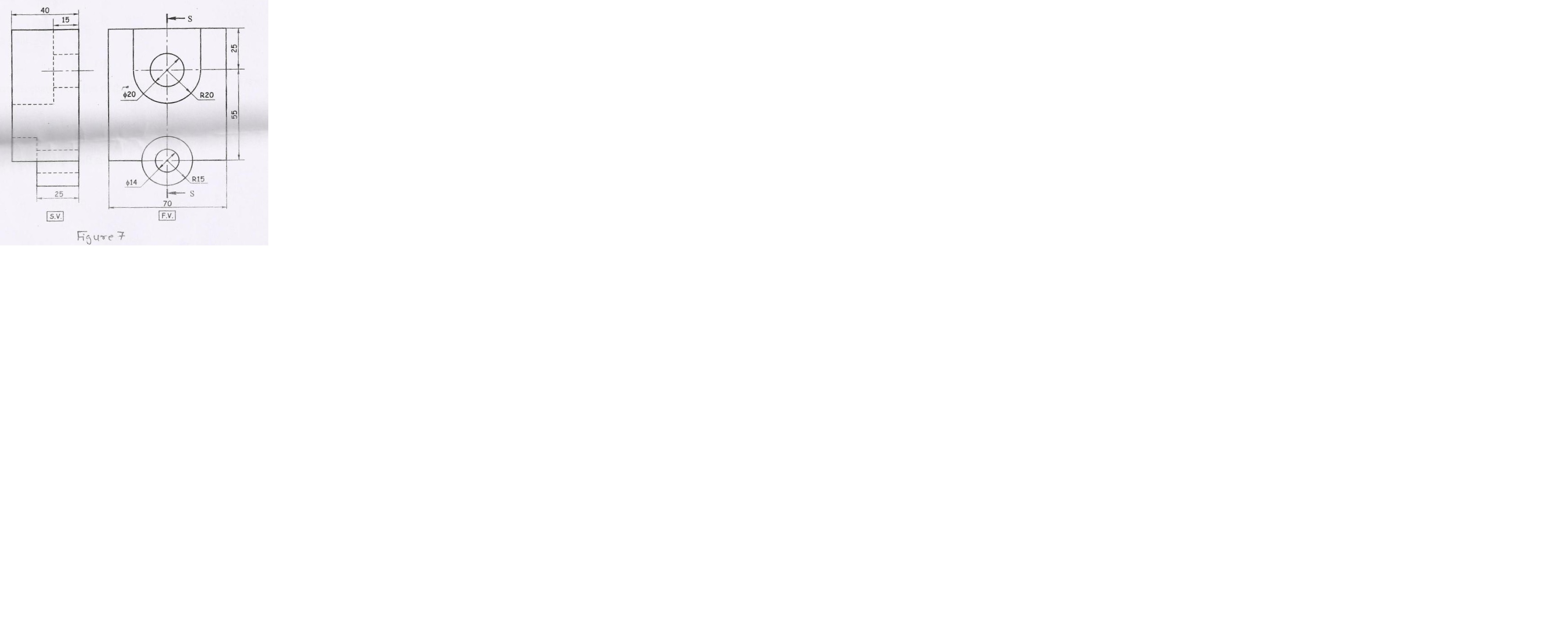
a) Sectional side view, along section S-S [7]
b) Top view [7]
c) Front view [3]
d) Dimensioning [3]
OR
Q10. The figure 8 shows front view and right side view of a machine part. Draw [20]
a) Sectional side view, along section A-A [7]
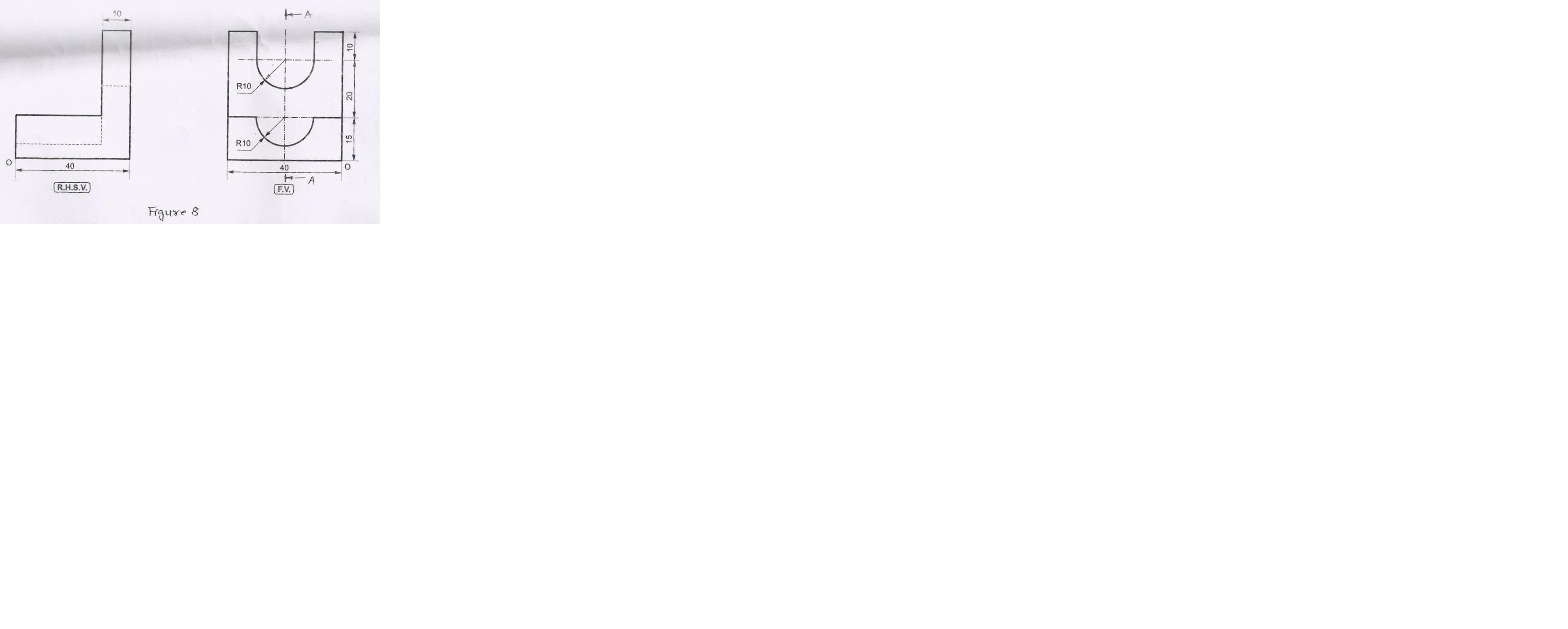
b) Top view [7]
c) Front view [3]
d) Dimensioning [3]
UNIT-VII: FREE HAND SKETCHES
Q11. Draw freehand sketches of the following: [10]
A) Square thread [3]
B) Leaf spring [3]
C) Single riveted lap joint [4]
OR
Q12. Draw proportionate freehand sketches of the following: [10]
a) Square nut [3]
b) Lifting eye bolt [3]
c) Gib-headed Key assembled in shaft and hub [4]
| Earning: ₹ 10.00/- |